3.17. Example Measurement Setups
The M81-SSM can be configured for a wide variety of measurements. The following examples show the recommended wiring for a few common applications.
Impedance Measurement
High-precision, high-accuracy modules are capable of measuring impedance ranging from micro-ohms to gigaohms. Lock-In Mode and AC sourcing capabilities allow for characterization of complex impedances.
Current source with voltage measurement
BCS-10 and VM-10 modules
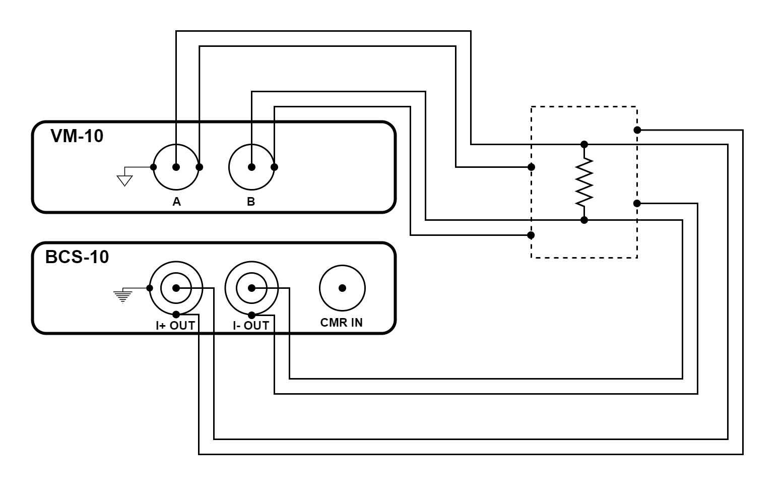
Figure 3.42 Resistance measurement using a BCS-10 module and a VM-10 module
The configuration illustrated above is a four-wire resistance measurement. It accurately determines resistance from milliohms to over a hundred megaohms. Guarded triaxial current source connections improve accuracy and settle time when measuring large resistors. This configuration resolves micro-ohm changes when set up to do lock-in measurements.
The configuration uses the balanced current source (BCS-10) module to provide current and measures the resulting voltage with the voltage measure (VM-10) module.
Earth and measure ground are connected together at the enclosure. The outer shell of the BCS-10 triaxial connectors provides earth ground while the outer shell of the VM-10 BNC connectors provides measure ground.
SMU-10 module
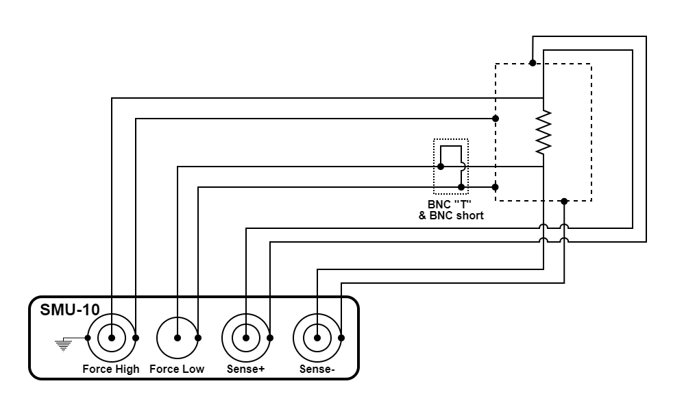
Figure 3.43 Four-wire resistance measurement using an SMU-10 module
The configuration illustrated above is a four-wire resistance measurement. The SMU-10 is configured to source current from the force hi terminal and measure voltage via the remote sense terminals. It accurately determines resistance from milliohms to over a hundred megaohms. This configuration resolves micro-ohm changes when set up to do lock-in measurements.
The configuration uses the source measure unit (SMU-10) module
Earth and measure ground are connected together at the enclosure. The outer shell of the SMU-10 connectors provide earth ground while the center pin of force low provides measure ground. A BNC “T” and a BNC short ties the two grounds together.
Voltage source with current measurement
VS-10 and CM-10 modules
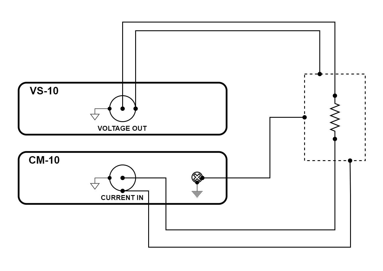
Figure 3.44 Resistance measurement using a VS-10 module and a CM-10 module
The configuration illustrated above is a two-wire resistance measurement. It is capable of accurately determining resistance from a few ohms to over a hundred gigaohms. This configuration can resolve micro-ohm changes when set up to do lock-in measurements.
The configuration uses the voltage source (VS-10) module to provide voltage and measures the resulting current with the current measure (CM-10) module.
Earth and measure ground are connected together at the enclosure. Earth ground is connected using a screw on the rear of the CM-10 module. The BNC shells of the modules provide measure ground.
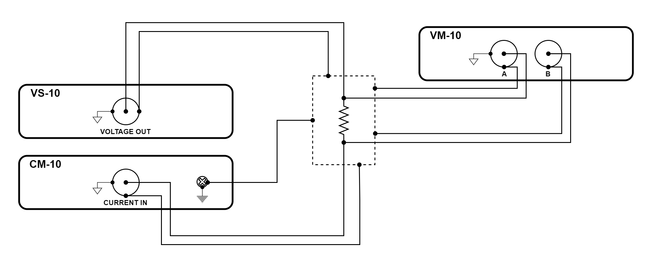
Figure 3.45 Resistance measurement using VS-10, CM-10, and VM-10 modules
Adding a VM-10 module to this configuration provides a four-wire measurement. This improves the accuracy of measuring small resistances.
SMU-10 module
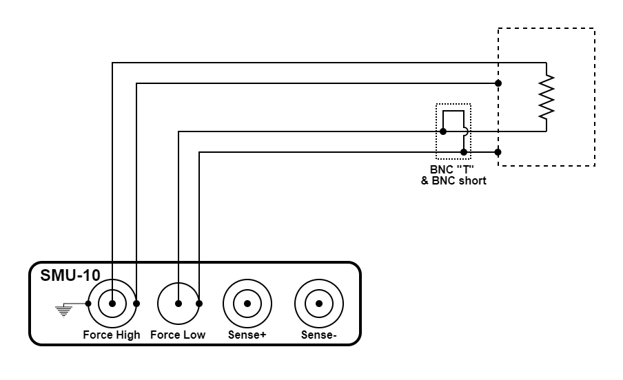
Figure 3.46 Two wire resistance measurement using an SMU-10 module
The configuration illustrated above is a two-wire resistance measurement. The SMU-10 is configured to source voltage and measure current. It accurately determines resistance from a few ohms to over a hundred gigaohms. The guarded triaxial current source connection improves accuracy and settle time when measuring large resistors.
The configuration uses the source measure unit (SMU-10) module
The outer shell of the force high connector provides earth ground while the center pin of force low connector provides measure ground. A BNC “T” and a BNC short ties the earth and measure grounds together near the enclosure.
Diode Characterization
The parameter sweeping feature and the data streaming feature allow for rapid I-V characterization. Lock-In Mode and AC sourcing capabilities allow for highly sensitive measurements.
VS-10, CM-10, and VM-10 modules
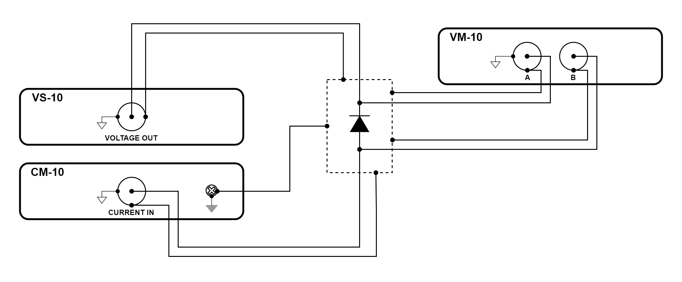
Figure 3.47 Diode measurement using VS-10, CM-10, and VM-10 modules
The configuration illustrated above is a four-wire diode measurement. It is capable of quickly and accurately determining the I-V characteristics of a diode.
The configuration uses the voltage source (VS-10) module to provide voltage and measures the resulting current with the current measure (CM-10) module. A voltage measure (VM-10) module creates a four-wire measurement to improve accuracy when the diode is conducting large amounts of current.
Earth and measure ground are connected together at the enclosure. Earth ground is connected using a screw on the rear of the CM-10 module. The BNC shells of the modules provide measure ground.
SMU-10 module
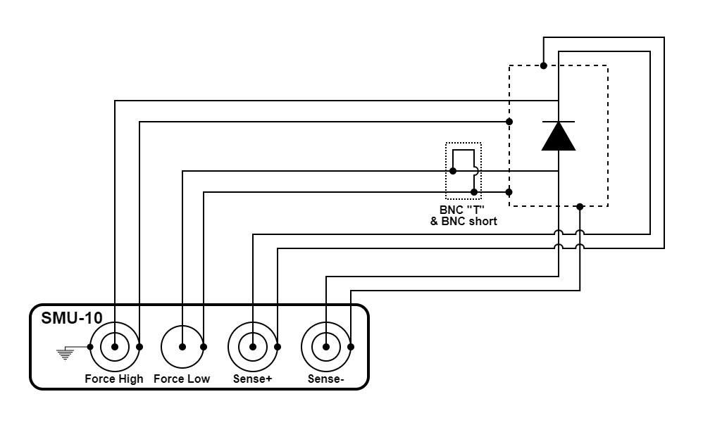
Figure 3.48 Diode measurement using an SMU-10 module
The configuration illustrated above is a four-wire diode measurement. It is capable of quickly and accurately determining the I-V characteristics of a diode.
The SMU-10 is configured to source voltage and measure current. The configuration uses the source measure unit (SMU-10) module. The source voltage can be configured to use remote voltage sense mode to maintain a consistent voltage across the diode even when the diode is conducting large amounts of current.
The outer shells of the connectors provide earth ground while the center pin of force low connector provides measure ground. A BNC “T” and a BNC short ties the earth and measure grounds together near the enclosure.
Transistor Characterization
The three source and three measure channels of the M81-SSM are easily synchronized to characterize multi-terminal devices such as transistors. The parameter sweeping feature and the data streaming feature allow for rapid I-V characterization. Lock-In Mode and AC sourcing capabilities allow for highly sensitive measurements.
Field Effect Transistor
VS-10 and CM-10 modules
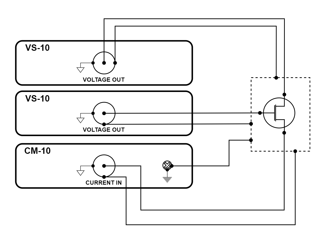
Figure 3.49 FET transistor measurement using VS-10 and CM-10 modules
The configuration illustrated above is a FET transistor measurement. This configuration can quickly and accurately determine the I-V characteristics of a FET transistor.
The configuration uses two voltage source (VS-10) modules to provide voltage to the gate and drain terminals. The current measure (CM-10) module holds the source terminal at 0 V.
Earth and measure ground are connected together at the enclosure. Earth ground is connected using a screw on the rear of the CM-10 module. The BNC shells of the modules provide measure ground.
SMU-10 module
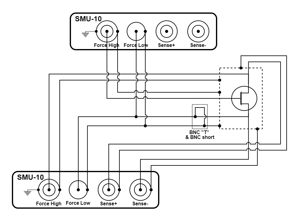
Figure 3.50 FET transistor measurement using two SMU-10 modules
The configuration illustrated above is a FET transistor measurement using two SMU-10 modules. It is capable of quickly and accurately determining the I-V characteristics of a FET transistor. The configuration uses the source measure unit (SMU-10) module.
Both SMUs are configured to source voltage and measure current. One SMU controls the voltage at the drain terminal and one SMU controls the voltage at the gate terminal. This configuration is able to monitor leakage current at the gate. The drain SMU can be configured to use remote voltage sense mode to maintain a consistent voltage across the transistor even when the transistor is conducting large amounts of current.
The outer shells of the connectors provide earth ground while the center pin of the force low connectors provide measure ground. A BNC “T” and a BNC short ties the earth and measure grounds together near the enclosure.
Configuring Unused Modules
When using the M81-SSM with multiple modules, it is often the case that not every module will be used in each experiment. To maintain measurement accuracy and prevent interference, either unload unused modules or follow these steps:
Set the output of all unused sources (VS-10 or BCS-10) to the disabled state.
Configure the input of any unused VM-10 to be grounded.
Turn off autorange for any unused CM-10 and set the range to 100 mA.