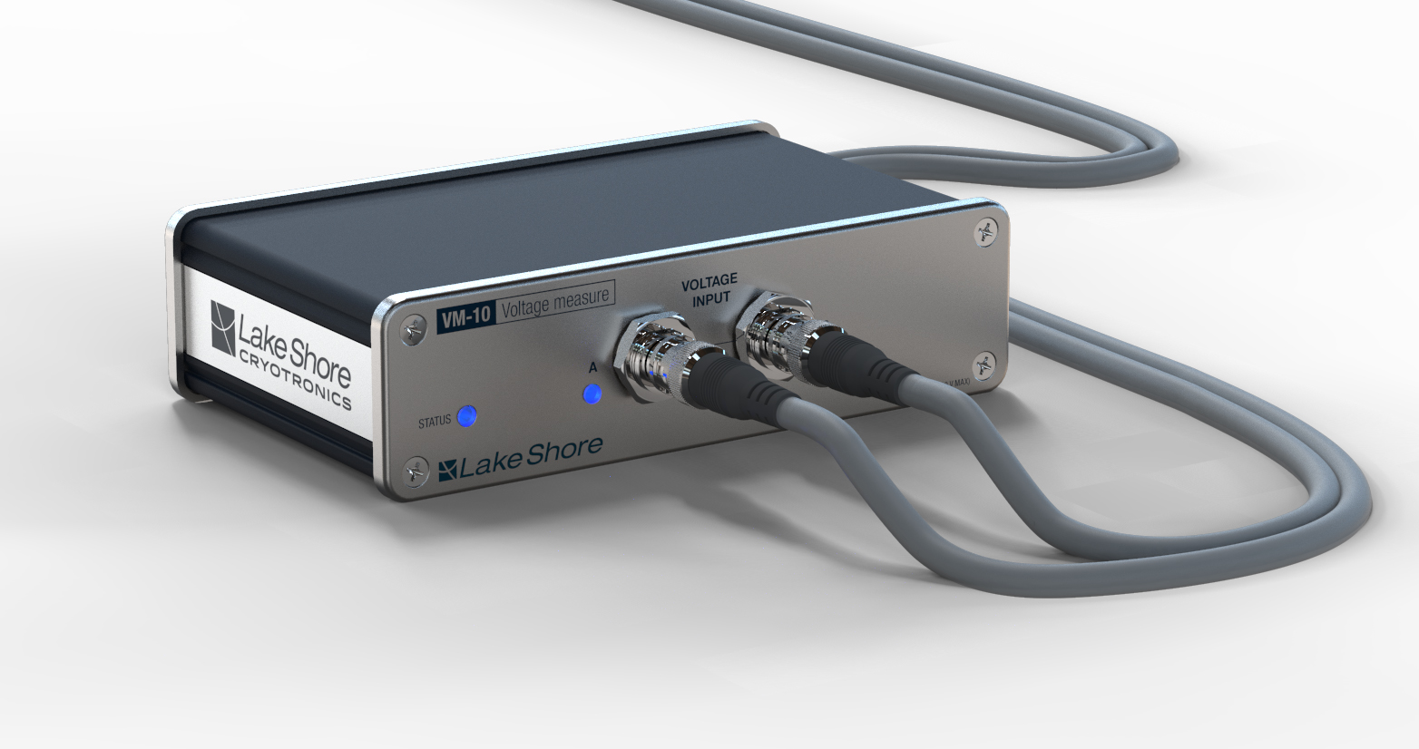
4.4. VM-10
The VM-10 is a single-ended or differential voltage measurement amplifier that can operate up to 10 V.
The VM-10 provides:
Single-ended (A) or differential (A-B) voltage measurement
Configurable ranges from 10 V to 10 mV
Seamless range changes
Configurable AC input coupling
A configurable hardware filter
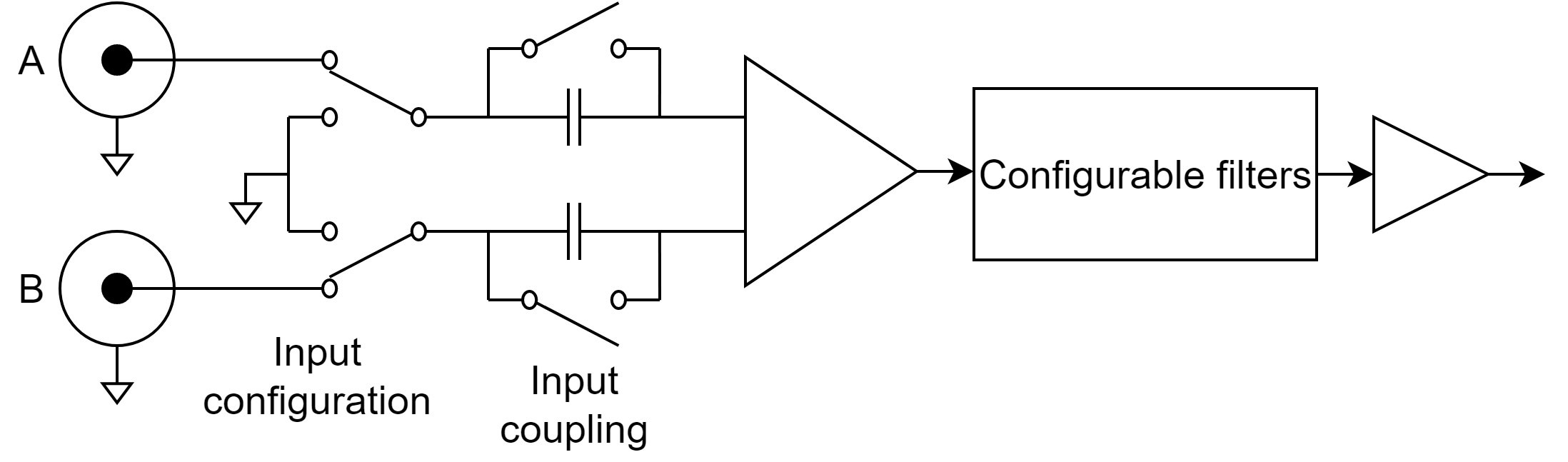
Figure 4.11 Module equivalent diagram
The settings for the VM-10 can be configured on the page for the module:
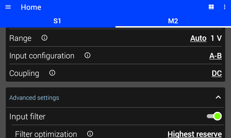
Figure 4.12 VM-10 settings
Range
The range determines the largest voltage that can be measured by the module. In general, the lowest range that can be used will provide the best performance. See instrument specifications for the performance characteristics of each range. The list of range bandwidths can be located on the instrument by tapping the info circle on the range setting.
If auto is selected, the VM-10 will automatically change ranges based on the input signal. The autoranging algorithm uses the maximum and minimum peak measurements to make decisions. The algorithm will observe the signal over the specified averaging time or time constant before making a decision. Therefore it will take longer to change ranges when the averaging time is longer, for example when there is a large number of NPLCs.
Available ranges are 10 V, 1 V, 100 mV, and 10 mV.
Note
The 10 V and 1 V ranges are not available when the analog input filter is enabled and filter optimization is set to lowest noise.
Input Configuration
The input configuration determines what voltage is measured by the VM-10.
A-B The VM-10 measures the difference between the voltage on input A and input B.
A The VM-10 measures the voltage between input A and measure ground.
Ground The input is internally connected to measure ground.
The indicator LEDs on the VM-10 will change to indicate what inputs are presently being used by the measurement.
Interface Command: SENSe#:CONFiguration
Input Coupling
If Coupling is set to AC, a high-pass filter with a cut-off frequency of 0.16 Hz is engaged. This blocks DC signals from being amplified but may reduce measurement accuracy. The input coupling is independent of the analog input filters.
Interface Command: SENSe#:COUPling
Note
The VM-10’s input bias current will cause a small DC offset voltage when coupling is set to AC. AC coupling should not be used when DC measurements are needed.
Analog Input Filter
The VM-10 has the capability to filter the input signal. Both a high-pass and low-pass filter are available. The analog input filters are configurable first or second order Butterworth filters.
This filter is a hardware filter located in the module. This is in addition to any digital filtering configured in the M81-SSM. This is useful for rejecting large interfering signals and preventing them from being amplified.
The low-pass filter removes high-frequency signals and preserves low-frequency signals. The high-pass filter removes low-frequency signals and preserves high-frequency signals. The low-pass and high-pass filters can be used together to create a band-pass filter, though there may be some reduction in signal amplitude.
Filter Optimization
In lowest noise mode, some gain is placed before the filters. This configuration provides the lowest noise, but causes overloads if an interfering signal is too large.
In highest reserve mode, all gain will be placed after the filters. This configuration can tolerate the largest interference, but the noise is higher.
Note
The 10 V and 1 V measurement ranges are not available when the analog input filter is enabled and filter optimization is set to lowest noise.
Optimization
The VM-10 can apply gain before and/or after the filter. The gain allocation is controlled with the Filter optimization setting.
In Lowest noise mode, some gain is placed before the filters. This configuration provides the lowest noise, but causes overloads if an interfering signal is too large.
In Highest reserve mode, all gain will be placed after the filters. This configuration can tolerate the largest interference, but the noise is higher.
Corner Frequency
The corner frequency can be selected from the listed options for each filter. If the corner frequency is set to None, the filter is disabled. When the Rolloff is set to 6 dB/oct, the gain of the filter will be 0.707 at the corner frequency. When the Rolloff is set to 12 dB/oct, the gain of the filter will be 0.5 at the corner frequency.
Rolloff
Each filter can be configured for single pole (6 dB/oct, first order) or two pole (12 dB/oct, second order) operation.
Default Settings
The table below lists the settings of the VM-10 upon initial power on or after settings are reset. For more information about default settings see the Default settings section.
Setting |
Default state |
|---|---|
Mode |
DC |
Averaging time |
3 NPLC |
Range |
Auto, 10 mV |
Input configuration |
A-B |
Coupling |
DC |
Analog Input filter |
Disabled |
Filter optimization |
Lowest noise |
Low-pass corner frequency |
None |
Low-pass rolloff |
6 dB |
Dark mode |
Disabled |