3.3. Basic Measurement Operation
To configure a measure module on the front panel, navigate to the tab for the module. NOTE: additional settings as applicable to a specific module will also be displayed. For information on those settings, see Modules.
Mode setting: determines what type of processing (DC, AC, or Lock-in) is performed by the M81-SSM on the signal received from the module. The other settings displayed will change based on what is relevant in the selected mode.
DC Mode
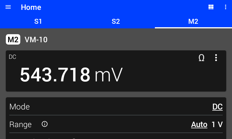
Figure 3.9 DC mode
Display
In DC mode, configure the display to show either the DC measurement, Relative DC measurement, or calculated resistance. Tap the three dots or the omega (Ω) in the upper right-hand corner of the display area to change which value is displayed. When displaying the Relative DC measurement, use the ZERO/CLEAR button to modify the baseline for the relative measurement. For more information on the calculated resistance, see Calculated Resistance. For more information on the Relative DC measurement, see Relative Measurement.
Averaging Time
The DC averaging time is specified in number of power line cycles (NPLC).
Note
The MeasureReady™ M81-SSM detects the power line frequency in your region.
While the M81-SSM ADCs sample at 375 kHz, the processed readings are made available at 5 kHz (200 μs per reading). This converts to an averaging time resolution of 0.01 PLC in 50 Hz line frequency regions and to 0.012 PLC in 60 Hz line frequency regions. If the requested is not a multiple of the time resolution, the actual averaging time will differ slightly from the requested averaging time. For example, if the power line frequency is 60 Hz, the minimum NPLC is 0.012. Setting an averaging time of 3 PLC would apply as-is and convert to an averaging time of 0.05 s. Setting an averaging time of 1 PLC would actually apply 0.996 PLC and convert to an averaging time of 0.166 s. Requested and actual NPLC values can be seen by tapping the info circle on the averaging time setting, or by querying via SCPI commands.
For best rejection of line-related interference in the DC measurement, an integer number of NPLC should be selected.
AC Mode
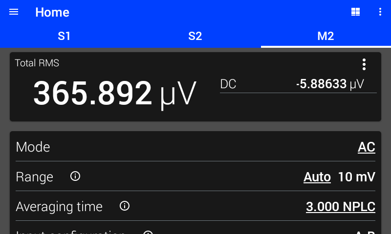
Figure 3.10 AC mode
Display
In AC mode, the display can be configured to show either total RMS and DC measurements, relative RMS measurement, or +Peak, -Peak, and Peak to Peak measurements. Tap the three dots in the upper right hand corner of the display area to change what is displayed. When displaying the Relative RMS measurement, use the ZERO/CLEAR button to modify the baseline for the relative measurement. For more information on the Relative RMS measurement, see Relative Measurement.
Total RMS The total power of the input signal, including AC and DC components within the observation window
DC The DC level of the input signal
+Peak The highest input level detected during the observation window
-Peak The lowest input level detected during the observation window
Peak to Peak The span between the highest and lowest input levels detected during the observation window
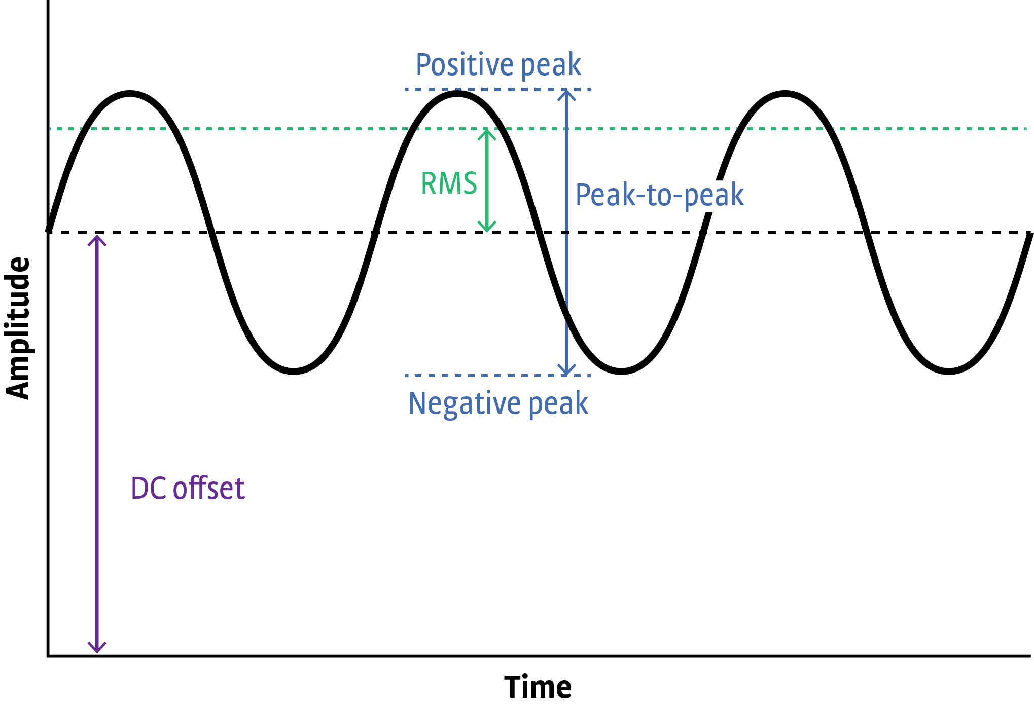
Figure 3.11 Available measurements in AC mode
Averaging Time
The RMS measurement and peak detection windows are specified in number of power line cycles (NPLC).
Note
The MeasureReady™ M81-SSM detects the power line frequency in your region.
While the M81-SSM ADCs sample at 375 kHz, the processed readings are made available at 5 kHz (200 μs per reading). This converts to an averaging time resolution of 0.01 PLC in 50 Hz line frequency regions and to 0.012 PLC in 60 Hz line frequency regions. If the requested is not a multiple of the time resolution, the actual averaging time will differ slightly from the requested averaging time. For example, if the power line frequency is 60 Hz, the minimum NPLC is 0.012. Setting an averaging time of 3 PLC would apply as-is and convert to an averaging time of 0.05 s. Setting an averaging time of 1 PLC would actually apply 0.996 PLC and convert to an averaging time of 0.166 s. Requested and actual NPLC values can be seen by tapping the info circle on the averaging time setting, or by querying via SCPI commands.
Lock-In Mode
In lock-in mode, the M81-SSM detects signals that are coherent with the configured reference signal. For more information about the underlying concepts of lock-in operation, see section Lock-In Amplifier Background.
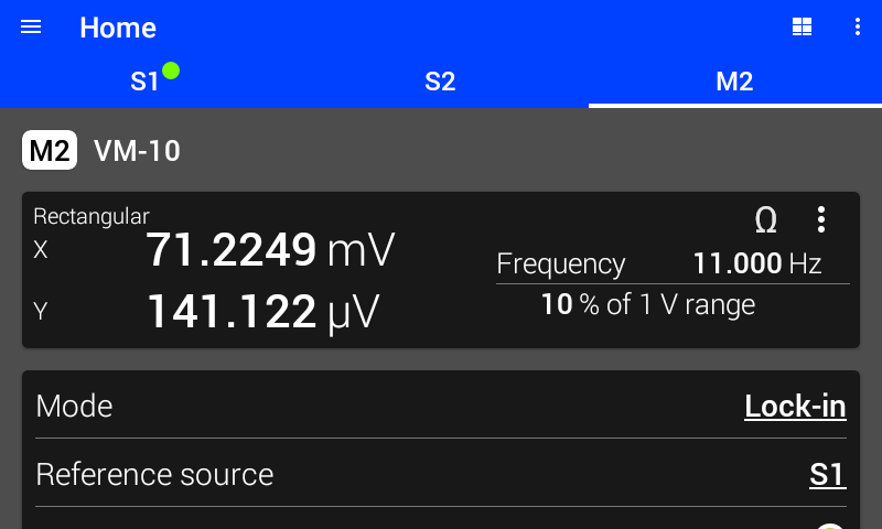
Figure 3.12 Lock-in mode display
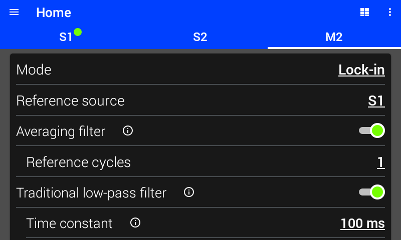
Figure 3.13 Lock-in mode settings
Display
In lock-in mode, the display can be configured to show either rectangular coordinates (\(X\), \(Y\)), polar coordinates (\(R\), \(θ\)), or the calculated resistance. In addition, the percent of range and frequency are always displayed. Tap the three dots or the omega (Ω) in the upper right hand corner of the display area to change what is displayed. For more information on the calculated resistance, see Calculated Resistance.
X The real (in-phase) component of the detected signal
Y The imaginary (quadrature) component of the detected signal
R The magnitude of the detected signal
θ The phase of the detected signal relative to the reference signal
% of Range The amount of the present range being used by the total input signal, including any noise. Tap on the reading to switch between % of range and lock-in DC measurement
Frequency The frequency of the reference signal
DC The DC component of the detected signal. The averaging time of the DC component is determined by the number of reference (FIR) cycles
Lock-In DC Measurement
The M81-SSM can measure the DC component of a signal while in lock-in measure mode. This is only available when the High-Pass Digital Filter is enabled. The averaging time of this DC measurement is equal to the length of the lock-in averaging filter. If the averaging filter is disabled, the length is equal to one cycle of the reference frequency. Tap on the reading to switch between % of range and lock-in DC measurement.
Interface Command: FETCh:SENSe#:LIA:DC?
Reference Source
The measure channel detects frequencies which are coherent with the specified reference source. For example, if a sample is being excited with a current by S1, the reference source can be set to S1. The reference source can also be set to Ref In, which will track the frequency detected on the reference input.
When reference source is set to a source channel, two additional read-only settings will appear. These settings display the amplitude and offset for the specified source module. However, the states below may be shown:
Disconnected The selected source channel does not have a source module connected.
Unloaded The selected source channel has a source module connected, but the source module is not loaded.
Module error The selected source channel has an error on the module, which can be viewed by selecting the relevant source channel tab.
Interface Command: SENSe#:LIA:RSOurce
Averaging Filter
When this filter is enabled, a separate FIR filter is applied to the phase-sensitive detector (PSD) output in addition to the Traditional low-pass (standard IIR) output filter specified by the time constant and rolloff settings. This FIR filter is a moving average over a configurable number of cycles (periods) of the carrier frequency. This additional filter helps reject the carrier and harmonics of the carrier when making lock-in measurements.
Interface Command: SENSe#:LIA:AVERage[:STATe]
Traditional Low-pass Filter
The traditional low-pass IIR filter is used to attenuate/reject signals outside of its pass band. Unlike the frequency response of the FIR filter, the IIR does not “bounce” and allow certain frequencies through. This means that if there is a large interfering signal the IIR will remove it better than the FIR.
However because of the exponential settling behavior of the IIR filter, it can take a long time for a measurement to be acceptably settled. Any input changes will remain in the IIR filter forever, getting smaller as time goes on but never going away completely. This means that large input disturbances can remain as errors in the lock-in measurement for a long time.
Interface Command: SENSe#:LIA:LPASs[:STATe]
Time Constant
The time constant setting determines the bandwidth of the PSD output filter. Longer time constants will result in lower equivalent noise bandwidth (ENBW) at the cost of longer settle times. See table below.
Interface Command: SENSe#:LIA:TIMEconstant
Rolloff
The rolloff setting determines the slope of the PSD output filter in the stop band. Steeper rolloff will result in lower ENBW at the cost of longer settle times, and will provide better rejection of interfering signals that are near the frequency of interest.
Interface Command: SENSe#:LIA:ROLLoff
For time constant \(\tau\), the ENBW and time to settle can be seen in the choosing lock-in filter settings table.
Reference Harmonic
The reference harmonic can be set to detect signals at a frequency that is a harmonic of the reference. For example, if the reference frequency is 1 kHz, setting reference harmonic to 2 would result in detecting signals at 2 kHz, which are coherent with the reference.
Interface Command: SENSe#:LIA:DHARmonic
Reference Phase Shift
The reference phase shift is applied to the reference source before using the reference for demodulation. Tap auto to set the phase shift to result in zero degrees of indicated angle. NOTE: the measurement should be settled before tapping auto. Tap clear to set the phase shift to zero.
Interface Command: SENSe#:LIA:DPHase