3.16. Parameter Sweeping
The M81-SSM system supports high-speed, synchronized parameter sweeps across one or more source modules. This feature allows users to automatically vary a single source parameter—such as voltage, current, frequency, or offset—over a defined range and duration, while simultaneously capturing measurement data from one or more measure modules.
Parameter sweeping is especially useful for characterizing device behavior under varying stimulus conditions. For example:
I-V Curve Measurement: Sweep voltage or current to measure the corresponding response and generate I/V curves for semiconductor devices. For diodes, this reveals forward conduction thresholds and reverse breakdown behavior. For transistors, such as FETs and BJTs, it helps characterize regions of operation, including cutoff, linear, and saturation modes.
Frequency Response Testing: Vary input frequency while measuring output amplitude or phase to evaluate system bandwidth, resonance, or filter characteristics.
Differential Conductance Measurement: Perform fine voltage sweeps around a bias point to calculate the derivative of current with respect to voltage (dI/dV), revealing subtle electronic transport features.
To fully utilize parameter sweeping, users must configure both:
A parameter sweep on a source channel.
A data stream on a measure channel to capture results.
See: Sweep Execution
Sweeps are performed synchronously across all configured source modules, and only one parameter may be swept per source at a time. Sweep settings are module independent, and must be configured for each channel in a multi-channel sweep.
For best results, users should also consider timing alignment between the dwell time, measurement averaging, and data streaming. See Timing Best Practices and Settling and Delay Behavior for more information.
Sweep Configuration Overview
To configure a parameter sweep:
Choose the parameter to sweep (voltage, current, frequency, or offset).
Set the sweep mode and configure relevant module settings.
Define sweep settings: span, duration, number of points, direction, and spacing.
Configure a data stream to collect measurements during the sweep.
Choosing the Sweep Parameter
Use SCPI commands to switch the sweep parameter from fixed to sweep mode. When the source module is in DC mode, the voltage or current DC level can be swept. When in AC mode, either the voltage/current amplitude, offset, or frequency can be swept.
Example: Sweep DC voltage on Source 1
SOURce1:FUNCtion:SHAPe DC
SOURce1:VOLTage:MODE SWEep
Sweep Settings
Span
The span is the difference between the start and stop values. Configure the span by setting both the start and stop voltage or the start and stop current of the sweep. When setting the span, it is possible to set the stop value lower than the start value. This will result in a sweep that decreases in value.
Note
The term “span” may be used elsewhere for the sake of explaining calculations.
Dwell Time
The amount of time the source output remains constant at each step of a parameter sweep. It defines how long the system waits at a given value before moving to the next point in the sweep.
Its primary use is to provide a stable window during which the measurement system can perform averaging and capture data. The length of the dwell time directly influences the timing of data acquisition and must be coordinated with measurement and streaming settings for accurate results. (see: Timing Best Practices)
Note
Dwell times are restricted to multiples of 200 µs per step, and must be a minimum of 200 µs.
When a dwell time is set to a value that is invalid, the instrument will adjust to the nearest valid value. For example, 0.0006 s is a valid dwell time. However, 0.0005 s is invalid, and the instrument will apply the dwell time of 0.0006 s, which can be seen with the relevant query.
It is also possible to define the total duration of the parameter sweep using the TIME command. In this case, the instrument will automatically calculate the closest valid dwell time that fits the specified duration and number of points.
Note
The total sweep time set by the TIME command represents the duration allocated for data acquisition. Additional time may be introduced by dynamic events such as source or measure range changes and hardware settling. These delays are not included in the calculated sweep duration and will extend the actual time required to complete the sweep.
User-defined blanking time, which is applied after each step to suppress transient effects, also adds to the total runtime. However, it is configured separately and is not factored into the TIME command’s calculation.
Points
The number of points defined in the stepped sweep. A higher value will create higher granularity in the span of the sweep, but will increase the total duration of the parameter sweep. Setting the number of points also directly affects the step size.
Setting the step size of the sweep will set the number of points according to the following formula: \(STEP = SPAN / (POINts - 1)\)
Note
The number of points specified should include the ending value.
For example, if the desired sweep is 0 V to 10 V with a step size of 1 V, the number of points should be 11.
The number of points can be set up to a maximum of 100,001 points, with a minimum of 2 points.
Note
Step cannot be set when using logarithmic spacing.
Direction and Round-Trip
The direction of the sweep controls whether the instrument sweeps up or down. While sweeping up, the sweep will begin at the start value and end at the stop value. When sweeping down, the sweep will begin at the stop value and end at the start value.
When round-trip sweeping is enabled, the instrument will begin and end at the same value. The instrument will repeat the middle value and double the number of points. For example, a sweep with a start value of 1, a stop value of 5, and 5 points would have these output values:
Direction: UP |
Direction: DOWN |
|---|---|
1 |
5 |
2 |
4 |
3 |
3 |
4 |
2 |
5 |
1 |
5 |
1 |
4 |
2 |
3 |
3 |
2 |
4 |
1 |
5 |
Spacing
Choose between linear or logarithmic spacing. Logarithmic sweeps cannot include zero.
Timing Best Practices
Accurate and meaningful data collection during a sweep depends on the relationship between Dwell Time, NPLC (Averaging Time), and Stream Rate. During each dwell period, the instrument can be configured to stream less than one point per step, exactly one point per step, or multiple points per step, depending on the measurement setup.
For high-resolution measurements, multiple points can be streamed per step by adjusting the stream rate and averaging time to fit within the dwell period. In other cases, a single data point may span multiple steps, which can be useful when speed is prioritized over per-step resolution.
MeasureLink simplifies this process by offering a Points per Step parameter in the M81 DC Sweep Measurement configuration. This setting automatically aligns the stream rate and averaging time with the dwell time.
Refer to the formulas and examples below to configure these parameters appropriately for your application.
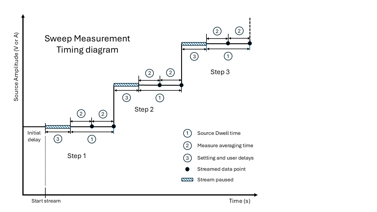
Figure 3.40 Two points streamed per step, Example 3 below
Key Parameters
Dwell Time: The duration the source signal remains at a specific value during a sweep step.
NPLC (Number of Power Line Cycles): Defines the averaging time for a measurement. Typically, NPLC = Dwell Time for full-duration averaging.
Stream Rate (Hz): The number of data points streamed per second.
Stream Rate Formula
n = Number of points to stream per step (must be an integer).
Valid range for n:
Averaging Time (NPLC)
i = Integer number of averaging cycles
1/i = Fraction of dwell time to average over
Example 1:
One point is streamed per step, and averaged over the entire dwell time. 60 Hz line frequency.
Dwell Time = 10 ms (0.010 s)
NPLC = 0.6 (entire dwell time)
n = 1
Stream Rate = 1 / 0.010 = 100 Hz
Example 2:
One point is streamed per step, but averaged over only half the dwell time. 50 Hz line frequency.
Dwell Time = 10 ms
NPLC = 0.25 (half of dwell time)
n = 1
Stream Rate = 1 / 0.010 = 100 Hz
Example 3:
Two points are streamed per step, each averaged over half the dwell time. 60 Hz line frequency.
Dwell Time = 10 ms
NPLC = 0.3
n = 2
Stream Rate = 2 / 0.010 = 200 Hz
Example Timing Configurations:
Points/Step (n) |
Dwell Time (s) |
Stream Rate (Hz) |
Averaging Time (s) |
Averaging Time (NPLC) @60Hz |
Averaging Time (NPLC) @50Hz |
|---|---|---|---|---|---|
1 |
1 |
1 |
1 |
60 |
50.0 |
1 |
0.1 |
10 |
0.1 |
6 |
5.0 |
1 |
0.01 |
100 |
0.01 |
0.6 |
0.5 |
1 |
0.001 |
1000 |
0.001 |
0.06 |
0.05 |
2 |
10 |
0.2 |
5 |
300 |
250.0 |
2 |
1 |
2 |
0.5 |
30 |
25.0 |
2 |
0.1 |
20 |
0.05 |
3 |
2.5 |
2 |
0.01 |
200 |
0.005 |
0.3 |
0.25 |
Settling and Delay Behavior
To ensure accurate measurements, the system applies delays to allow the hardware to settle after each step change. During these delays, data streaming and averaging are paused, meaning no data collection occurs.
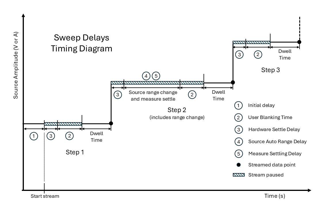
Figure 3.41 Two points streamed per step, Example 3 below
1. Initial Delay
Optional, user-defined delay at the beginning of the sweep. This is a one-time delay.
2. User Blanking Time
Optional, user-defined blanking time can be added after each step to exclude transient effects from measurements.
3. Hardware Settle Delay
For each sweep step, the system applies the maximum required hardware settle time across all active source and measure modules, depending on their ranges.
4. Source Auto Range Delay
If source auto ranging is enabled, the system checks whether the next output level requires a range change. If so, a delay is introduced before applying the new level.
The settling time is typically between 30 ms to 100 ms, depending on range.
5. Measure Settling Delay
A source range change always triggers a measure settle delay. This includes a go-to-zero sequence.
Measure modules may also auto range and trigger a settle delay depending on the change in output level, even if the source is in manual ranging. If the module is a VM-10, it will seamlessly change range without settling.
The measure settling delay is typically between 100 ms and 1.2 s, depending on range.
Sweep Execution
To run a sweep and collect data:
Configure the sweep on the source. see: Sweep Configuration Overview
Set up a data stream of the measure channel(s). see Configuring the Stream
Start the sweep using TRACe:STARt (with streaming) or SWEep:INITiate (without streaming).
A new sweep will not start if a sweep is already running.
Sweep Status and Aborting
Check sweep status:
SOURce1:SWEep:STATus?
Abort a sweep:
SWEep:ABORt
Sweeps also abort if: - A source setting is changed mid-sweep. - A data stream is reset.
Example: Current Sweep with Data Stream
The following example illustrates how to configure a current parameter sweep on the first source channel and read the resulting measured voltage on the first measure channel.
Set the source module to a linear sweep.
SOURce1:SWEep:SPACing LINear
SOURce1:CURRent:MODE SWEep
Set the source and measure ranges.
SOURce1:CURRent:RANGe 0.1
SENSe1:VOLTage:RANGe 1
Set the span of the sweep to start at 25 mA and end at 100 mA.
SOURce1:CURRent:STARt 0.025
SOURce1:CURRent:STOP 0.100
Set the dwell time to 5 ms per step.
SOURce1:SWEep:DWELl 0.005
Set the measure averaging time (60 Hz line frequency).
SENSe1:NPLCycles 0.3
Set the number of points to 100, which is equivalent to a step size of 75 µA.
SOURce1:SWEep:POINts 100
Configure and start the data stream to begin the sweep and collect the data. Set the data stream to provide information in a comma-separated format. Set the data stream to provide the source channel 1 amplitude, measure channel 1 DC measurement, and measure channel 1 settling status. Set the data stream rate to 200 points per second to match the 5 ms dwell time.
TRACe:RESet
TRACe:FORMat:ENCOding CSV
TRACe:FORMat:ELEMents SAMP,1,MDC,1,MSET,1
TRACe:RATE 200
TRACe:STARt 100