3.2. Basic Source Operation
To configure a source module on the front panel, navigate to the tab for the module.
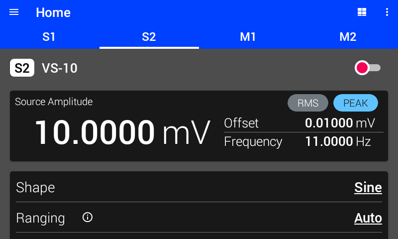
Figure 3.4 Basic source settings
Note that additional settings as applicable to a specific module will also be displayed here. For information on those settings, see Modules.
Enable/Disable
A source module’s output can be enabled or disabled with the slider switch. When the switch is red, the output is disconnected and no excitation is applied. When the switch is green, the output is connected and excitation is applied. Always make sure that all other settings are configured appropriately before enabling the output.
Interface Command: SOURce#:STATe
Shape
Amplitude
The source amplitude can be set by tapping the amplitude value in the display area and entering a new value. When shape is DC, the amplitude directly sets the total excitation level. When shape is not DC, the amplitude sets the peak level of the excitation waveform. When shape is SINE, the amplitude can also be set with the RMS command. The instrument will calculate the peak amplitude based on the value provided.
Frequency
Offset
The offset can be set by tapping the offset value in the display area and entering a new value. The offset is added to the excitation waveform allowing for simultaneous AC and DC excitation.
Note
Offset is not used if shape is DC and will be automatically configured to zero.
Duty
The duty cycle is the ratio of the excitation waveform that is active and is expressed as a % value between 0 and 1.0. It only applies to square and triangle shaped output. How the output is affected by the duty cycle is discussed in the following sections.
Square Wave Duty
Square wave source shape is a periodic waveform consisting of near instantaneous transitions between DC source values. The reciprocal of the source frequency determines the full period (high and low values) of a cycle while the source amplitude and offset determine the values of the high and low levels of the periodic source signal. At zero offset, the high and low values are the set value of the amplitude and the corresponding negative amplitude.
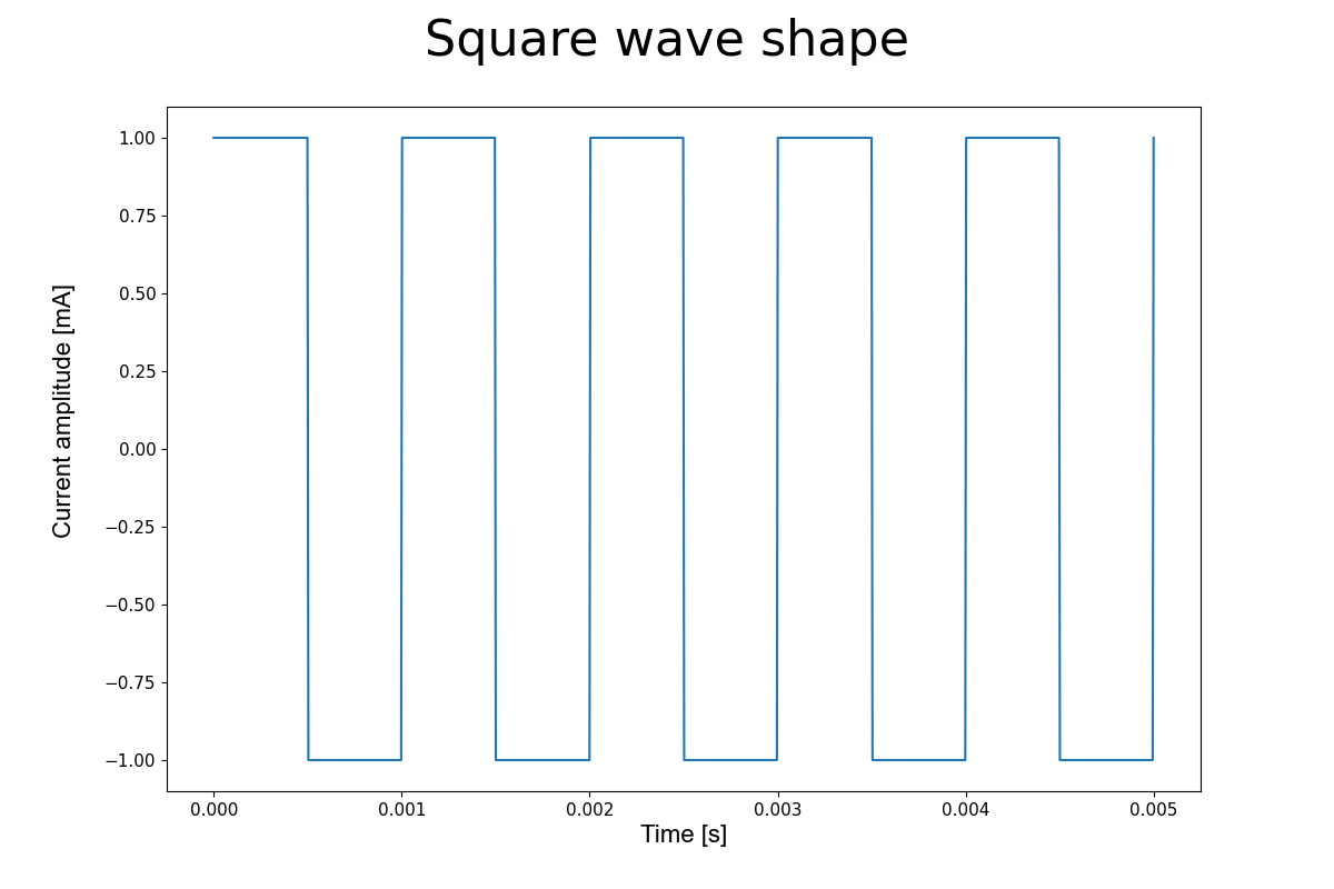
Figure 3.5 Square waveform shape
At 50% duty (duty: 0.500), the source value will spend equal time at the high and low setting of the waveform. The duty represents the fraction of the full cycle that the waveform spends at the high value; for values greater than 0.5, the periodic signal will spend more time at the high value and for values less than 0.5 the signal will be at the low value of the waveform for a comparatively longer time. For a square waveform on the M81-SSM, the duty can be set from values of 0.001 to 0.999 — that is 0.1% to 99.9% duty cycle. Duty values of 0 and 1 are valid inputs but will result in a constant or DC waveform.
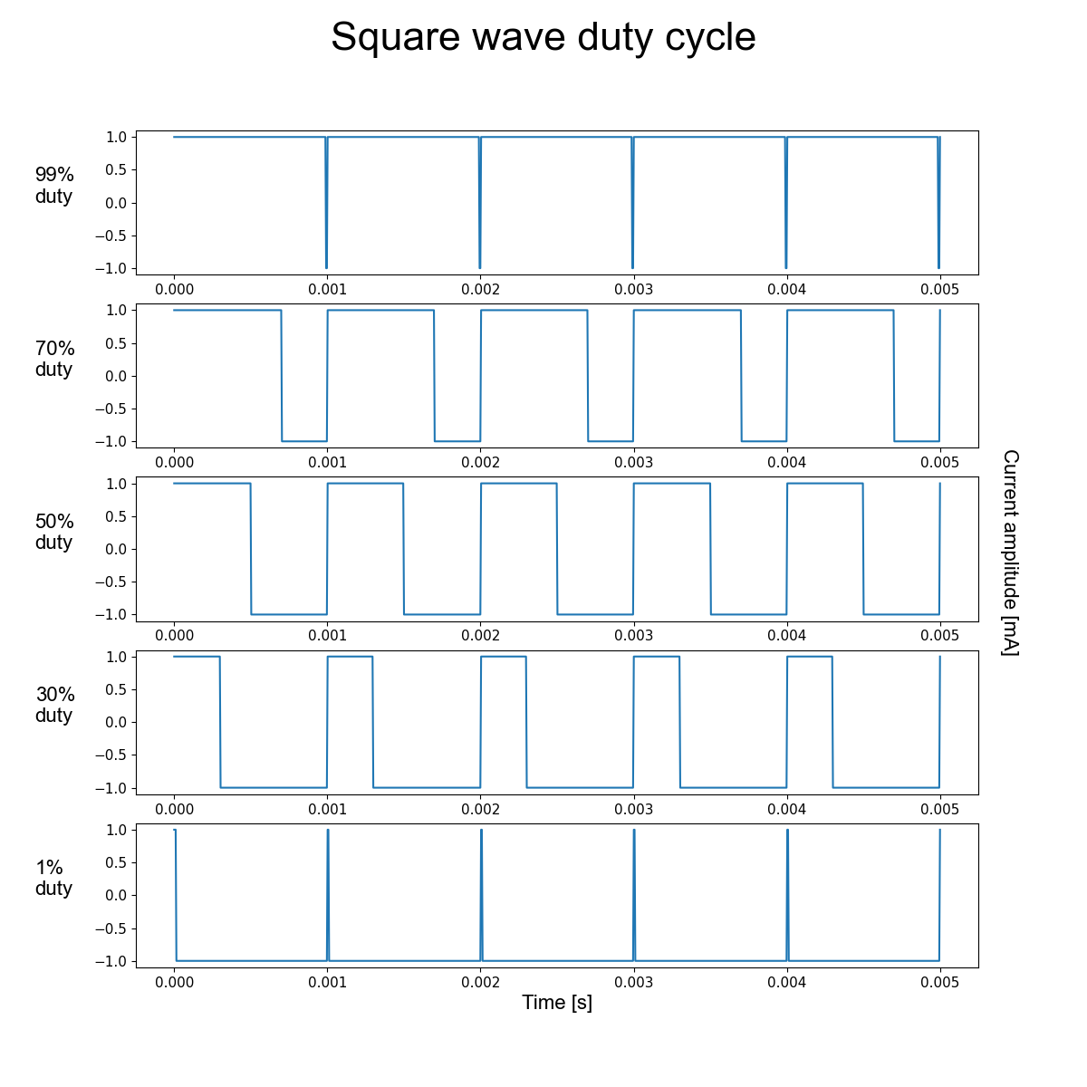
Figure 3.6 Duty setting changes the fraction of cycle time at the maximum DC value. Each trace has the same source frequency.
Triangle Wave Duty
The M81-SSM can also source triangle waveforms. With zero offset, the triangle wave is a periodic function consisting of a segment with source values that increase, linearly with time, from the negative amplitude value to the positive amplitude value and a second segment with source value that decreases, linearly with time, from the positive amplitude to the negative amplitude. The cycle period, consisting of both positive and negative slope segments, is the reciprocal of the waveform frequency.
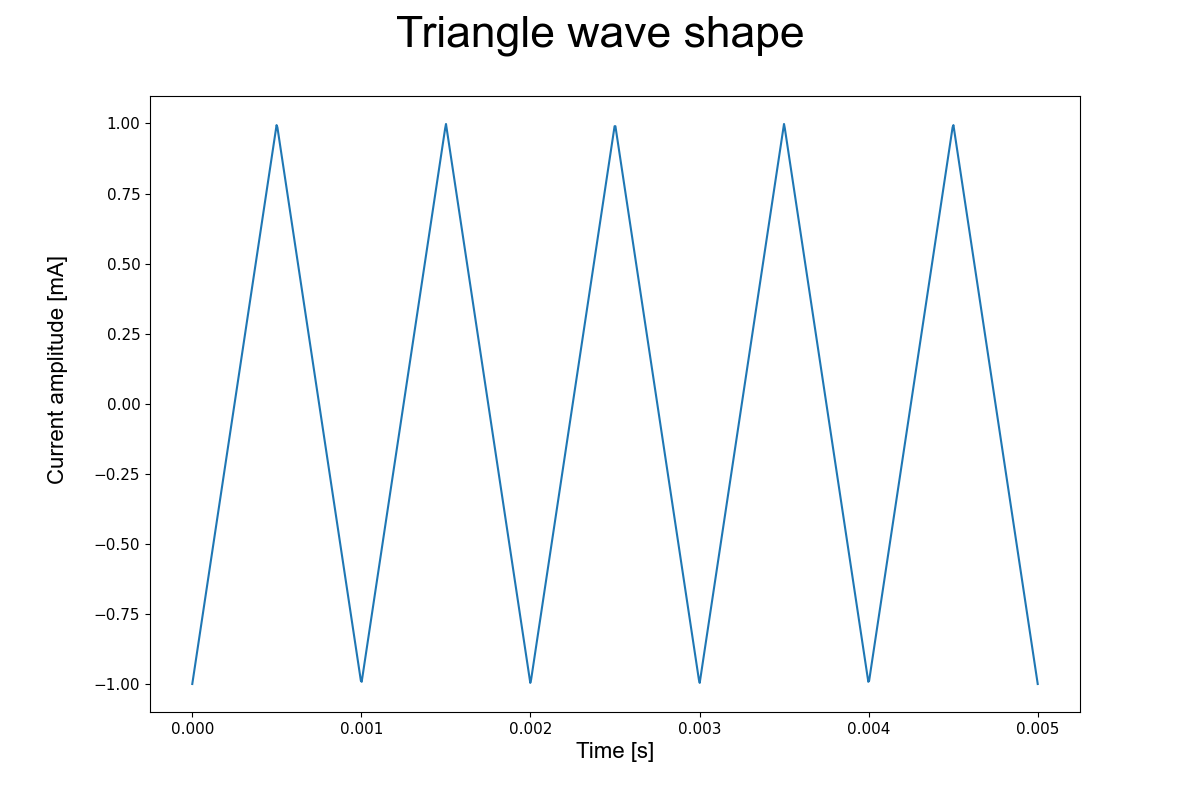
Figure 3.7 Triangle waveform shape.
With a triangle shape, the duty is defined by the fraction of the cycle period with positive slope. Just as with the square waveform, the duty can be set from 0 to 1 with 0.1% increments. Duty values greater than 0.5 generate waveforms with longer times with positive slope and duty values below 0.5 generate longer times with negative slope. With a duty setting of 0 or 1, the M81-SSM sources a so-called sawtooth waveform.
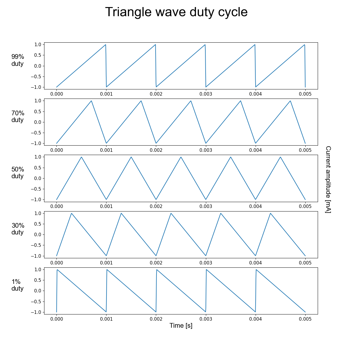
Figure 3.8 Duty sets the fraction of the cycle period with positive slope. Each trace has the same source frequency.