3.6. Advanced Measurement Operation

To configure advanced settings, scroll down to the advanced section, and tap it to expand.
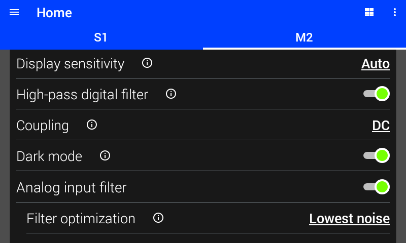
../_images/lia_advanced_settings.png

Figure 3.16 Advanced lock-in settings

FIR PSD Filter

When this filter is enabled, a separate FIR filter is applied to the PSD output in addition to the standard IIR output filter specified by the time constant and rolloff settings. This FIR filter is a moving average over a configurable number of cycles (periods) of the carrier frequency. This additional filter helps reject the carrier and harmonics of the carrier when making lock-in measurements.

Interface Command: SENSe#:LIA:FIR[:STATe]

IIR PSD Filter

The IIR filter is extremely good at attenuating/rejecting signals outside of its pass band. Unlike the frequency response of the FIR filter, the IIR does not “bounce” and allow certain frequencies through. This means that if there is a large interfering signal the IIR will do a better job of removing it than the FIR.

However because of the exponential settling behavior of the IIR filter, it can take a long time for a measurement to be acceptably settled. Any input changes will live on in the IIR filter forever, getting smaller as time goes on but never going away completely. This means that it can take a very long time for large input disturbances to no longer be a significant error in the lock-in measurement.

Interface Command: SENSe#:LIA:IIR[:STATe]

Digital Filter

When this filter is enabled, a high pass filter is applied to the lock-in readings before demodulation. The corner frequency of the filter adjusts automatically such that the response time of the lock-in measurement is not affected. The gain and phase of the filter is also compensated to avoid affecting the measurement. The filter is effective at reducing noise when measuring lock-in signals with large DC components, especially at low frequencies.

Interface Command: SENSe#:DIGital:FILTer:HPASs[:STATe]

Dark Mode

If dark mode is enabled, the indicator LEDs on the front of the module will be turned off.

Interface Command: SENSe#:DMODe

Calculated Resistance

By tapping the resistance “R” in the upper right hand corner of the display area, it is possible to view the calulated resistance when the measure module is in either dc or lock-in mode. To exit resistance view, either the three dots can be tapped to select the desired view, or the reading symbol can be tapped to return to the default view. When in dc mode, the display will show the selected source module’s excitation that is being used in addition to the resistance value. When in lock-in mode, the display will show the selected source module’s excitation and frequency in addition to the resistance value.

Presently, only two resistance calculations are supported. The first calculation requires a source module generating a DC shape with a measure module in DC mode. The second calculation requires a source module generating a sine shape with a measure module in lock-in mode.

In some cases, the resistance value may appear as an error code. These error messages can be tapped for more information about what is causing the issue.

  • S MISS The selected source module is not connected.

  • S UNL The selected source module is not loaded.

  • INVALID The source module is not compatible with the measure module for calculating resistance. This occurs when the two modules use the same units, such as a VM-10 and VS-10.

  • E TYPE The excitation type is not valid. This occurs when the measure mode and source shape do not create a supported resistance calculation.

  • DIV BY 0 The sourced or measured current is 0.

  • M ERR There is an active error on the measure module.

  • S ERR There is an active error on the selected source module.

Note

The displayed value may also show inaccurate noise values when the selected source is not enabled.

../_images/calculated_resistance_display.png

Figure 3.17 Lock-in resistance calculation

The source module being used to calculate resistance can be changed by scrolling down to the advanced section, and tapping to expand. The resistance is calcuated using one voltage and one current module. Therefore, for a module to be compatible, the source module must be voltage when the measure module is current, or vice versa.

Interface Command: CALCulate:SENSe#:RESistance:SOURce

Relative Measurement

Relative measurements allow the removal of offsets from measured readings that could be introduced by sources external to the experiment. By using the zero button, existing offset will be set into the baseline value which is subtracted from the primary reading being displayed. When a baseline value is set, the zero button will be replaced with a clear button, which will set the baseline value back to zero.

By tapping the 3 dots in the upper right hand corner of the display area, it is possible to select Relative DC or Relative RMS, when in DC or AC modes respectively. The zero and clear button will allow for quick modification of the baseline value, shown in the bottom left of the display.

../_images/relative_rms_measurement.png

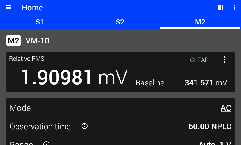
Figure 3.18 Relative RMS measurement

The baseline value can also be controlled by scrolling down to the advanced section, and tapping to expand. Tapping the advanced setting also allows for setting a custom baseline value.

../_images/relative_measurement_setting.png

Figure 3.19 Relative measurement setting and baseline value