4.3. BCS-10
The BCS-10 is a unique type of current source called a balanced current source. It provides up to 100 mA of DC and AC output current.
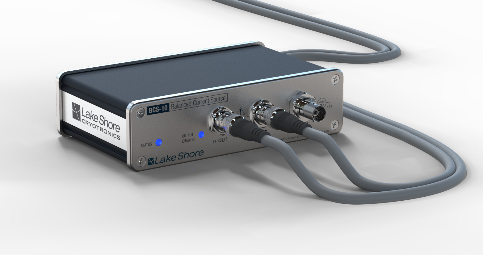
The BCS-10 provides:
A balanced current output
Configurable ranges from 100 mA to 10 nA
Common mode control
Configurable AC coupling
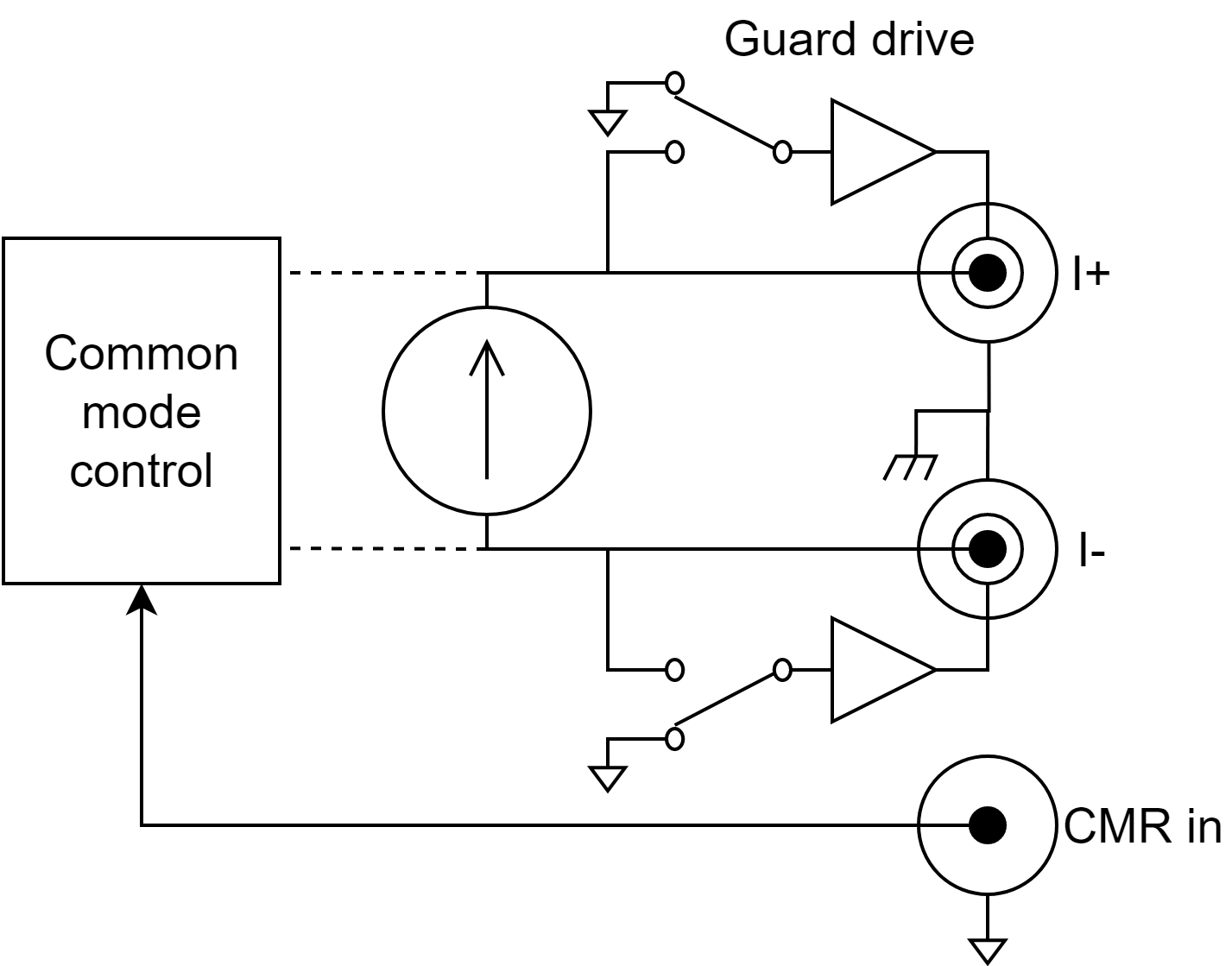
Figure 4.9 Module equivalent diagram
Configure the settings for the BCS-10 on the module page:
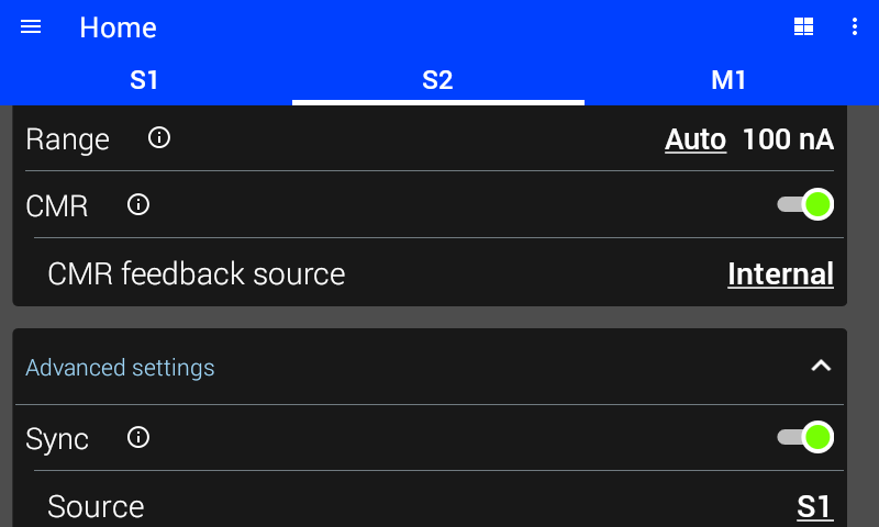
Figure 4.10 BCS-10 settings
Caution
If the BCS-10 is disconnected from a load, it will output the full compliance voltage of 20V. For sensitive devices, ensure that the source is disabled when connecting the module to the device. For devices that are sensitive to, or may be damaged by, such voltages, make sure that the source is disabled prior to disconnection from and/or re-connection to the device under test, or by adding external voltage limiting devices if such operation cannot be ensured.
Range
The range determines the largest current that can be sourced by the module. In general, the lowest range that can be used will provide the best performance. See instrument specifications for the performance characteristics of each range.
If Auto is selected, the M81-SSM selects the lowest current range that will support the amplitude, offset, and frequency each time they are configured.
The available ranges are 100 mA, 10 mA, 1 mA, 100 µA, 10 µA, 1 µA, 100 nA, and 10 nA.
Guard Drive
If guards are enabled, the inner sheath is driven with the voltage present on the center conductor. The guard minimizes effective capacitance and leakage current. In either setting, the guard should not be connected to ground.
Interface Command: SOURce#:GUARd
Coupling
If coupling is set to AC, signals below 1.6 Hz are blocked from the output. This minimizes offsets on the output if DC and low frequency signals are not needed. When coupling is set to DC, the BCS-10 has a low output impedance at low frequencies. DC coupling is needed when sourcing low frequencies or output shapes that have DC components such as square waves.
Interface Command: SOURce#:COUPling
Disable On Overload
If Disable on Overload is enabled, the BCS-10 firmware automatically disables the output when an overload is detected. NOTE: this feature is implemented in the firmware, and will not respond as instantaneously as a hardware implemented compliance would.
Interface Command: SOURce#:DOCompliance
High and Low Current Output Limits
The current output limits are software limits preventing the user from entering an output that could potentially damage the module’s load.
When the shape is not DC, the limit is applied to the sum of the offset and amplitude. Low current output limit is the minimum current that a user is allowed to enter, while the high current output limit is the maximum current the user is allowed to enter. Both current limits are bound between -100 mA and 100 mA with the expectation that the lower current output limit must be a lower value than the high current output limit.
Interface Command: SOURce#:CURRent:LIMit:HIGH Interface Command: SOURce#:CURRent:LIMit:LOW
CMF
The common mode feedback (CMF) (previously commond mode reduction - CMR) servo circuit controls the common mode voltage on the differential output of the current source.
Should CMF be on or off?
The BCS-10 is unique in that both the I+ and I- outputs are high impedance. This means that both the I+ and I- leads can be at any voltage between +10 V and -10 V. In many cases, there is no external low impedance path to measure common (for example, in a 4-wire resistor measurement with the VM-10). In such cases, CMF should be enabled. This means that the BCS will determine the operating voltage. In other cases, the load of the BCS may be grounded externally. In such cases, CMF should be disabled.
If CMF is on, should I use internal or external CMF?
In most applications, internal CMF is suitable. However, external CMF can be used to reduce errors arising from common mode voltage. This is especially relevant for low resistance measurements. Consider a 4-wire resistor measurement like the following:
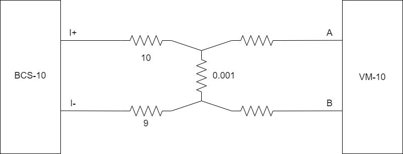
Suppose the BCS-10 is supplying a 100 mA excitation current. This current through a 1 mΩ device under test will produce a differential voltage of 100 µV. However, with internal CMF mode, the BCS will produce an average voltage of 0 on its output terminals. It will produce a common mode voltage of 100 mV because of the 1 Ω difference in the current leads. The VM-10 measures a 100 µV signal in the presence of 100 mV of common mode. The VM-10 has the ability to reject at least 80 dB of common mode. Even with this rejection, the VM will indicate 110 µV, resulting in a 10% error. This error can be resolved by using external CMF, connected as follows:
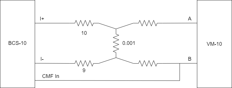
In external CMF mode, the BCS-10 adjusts the I+ and I- outputs to produce 0 V at the CMF sense point, which has been connected to the VM-10 B input. The VM-10 is presented with only 100 µV of common mode voltage, significantly reducing the error.
Default Settings
The table below lists the settings of the BCS-10 upon initial power on or after settings are reset. For more information about default settings see the Default settings section.
Setting |
Default state |
|---|---|
Shape |
DC |
Frequency |
11 Hz |
Amplitude |
0 pA |
Offset |
0 pA |
Ranging |
Auto, 10 nA |
Common mode feedback (CMF) |
Enabled |
CMF common mode node |
Internal |
Sync |
Disabled |
Sync source |
S1 (or S2 if module is S1) |
Sync phase shift |
0 degrees |
Guard drive |
Enabled |
Coupling |
Auto, DC |
Dark mode |
Disabled |
Disable on Overload |
Disabled |
High current output limit |
100 mA |
Low current output limit |
-100 mA |