3.8. Calculated Resistance
The M81-SSM facilitates resistance calculations by pairing measure modules with appropriate source modules, streamlining the configuration process for accurate and efficient measurements. Resistance calculations can be produced by a measure module paired with a source module, or a measure module paired with another measure module. See Resistance Source below.
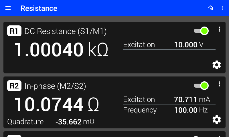
Figure 3.25 DC and AC resistance calculations
To access the Resistance screen, tap the omega symbol (Ω) located in the upper right corner of the screen. This screen provides a consolidated view of resistance calculations, organized into three panels, each representing a measure module. Tap the settings symbol located in the lower right corner of a panel to open a screen showing all relevant settings for the specified resistance calculation, with smart settings that simplify the setup process.
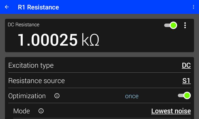
Figure 3.26 Resistance settings screen
In some cases, the resistance value may appear as an error. These errors are meant to help configure the correct settings necessary for a resistance calculation. Tap the error on-screen to see more information, and how to correct the error:
S# is not connected The selected resistance source is not connected. Connect and load the selected module or change the resistance source to another module that is connected and loaded.
S# is not loaded The selected source module is not loaded. Load the selected module or change the resistance source to a loaded module.
The units are not compatible The measure module is not compatible with the selected resistance source module. This occurs when both modules use the same units, such as a VM-10 and VS-10.
Measure mode and source shape are not compatible The excitation type is not valid. This occurs when the measure mode and source shape do not create a supported resistance calculation. For example, the measure module is set to DC mode while the source module has a Sine shape. A similar error occurs when two measure modules with difference modes are used in a resistance calculation.
The source amplitude is 0 The resistance source current is 0. Set a nonzero amplitude to calculate a resistance measurement.
M# is in error There is an active error on the measure module. Check connections and settings.
S# is in error There is an active error on the source module. Check connections and settings.
Note
The displayed value may also show inaccurate noise values when the selected source is not enabled.
Note
Multiple errors may be active, though only one appears at a time. Error priority is listed above.
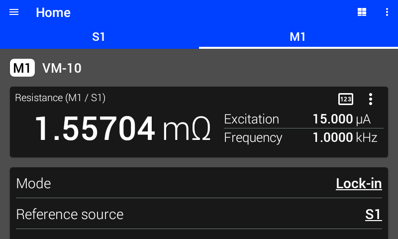
Figure 3.27 Simple DC resistance calculation
A simple resistance calculation with no smart settings is also possible. To access this calculation, navigate to a measure module readings panel and tap the resistor symbol in the upper right-hand corner of the display area. To exit the simple resistance view, either tap the three dots at the right side of the display area to select the desired view, or tap the reading symbol to return to the default view. When in DC mode, the display will show the selected source module’s excitation that is being used in addition to the resistance value. When in lock-in mode, the display will show the selected source module’s excitation and frequency in addition to the resistance value.
Resistance Source
Resistance calculations require two modules: one in units of voltage and one in units of current. Since these calculations are based on measure modules, an accompanying module must be selected as the resistance source. This resistance source can either be a source module or a measure module. To ensure compatibility, the selected resistance source must be a voltage module when the measure module is current, and vice versa.
Though two measure modules can produce a resistance measurement, they require a signal excitation into the resistor they are measuring. This can be provided by a source module, or an external source.
Updating the resistance source when the relevant measure module is in lock-in mode will update the lock-in reference source. However, changing the lock-in reference source will not update the resistance source.
Excitation Type
The Excitation type determines the mode of the active measure module, and the shape of the selected source module. This setting supports two types: AC and DC. Choose the correct excitation type to ensure the correct pairing of both modules for a resistance measurement.
When using a measure module and a source module:
AC The measure module is in Lock-in Mode and the source module is in Sine Shape.
DC The measure module is in DC Mode and the source module is in DC Shape.
Invalid The measure mode and source shape are not compatible for calculating resistance. Use AC or DC.
When using two measure modules:
AC Both measure modules are in Lock-in Mode.
DC Both measure modules are in DC Mode.
Invalid The measure modes are not compatible for calculating resistance. Use AC or DC.
When the Excitation type is set to AC, the measure module operates in lock-in mode. In this mode, the measure module features both a resistance source, and a lock-in reference source.
Note
The selected source module often serves as both the resistance source and the reference source.
In the case of an AC excitation type with two measure modules, and an additional source module supplying the excitation, both measure modules must have their reference source set to the source module. For example: a CM-10 (M1) and a VM-10 (M2) are both measuring the same resistor, while a VS-10 (S1) applies a voltage across that resistor. A resistance calculation should be configured on the CM-10 in channel M1, as follows:
The VM-10 (M2) is selected as the resistance source
Excitation type is set to AC
Because both M1 and M2 are in Lock-in mode, their reference sources are set to S1
If the source module is replaced with an external instrument, set both reference sources to Ref in.
DC Excitation type Display Modes
DC Excitation type provides the ability to calculate a relative DC resistance value. Tap the three dots in the upper right-hand corner of the resistance screen to select the desired view.
Relative DC mode allows for the removal of offsets from the calculated resistance value. By using the zero function, the existing resistance value will be set into the baseline value. This baseline value is then subtracted from the resistance value that is displayed.
Once a baseline value is set, the zero function will be replaced with a Clear option. Tap Clear to set the baseline value to 0, removing modifications to the resistance value.
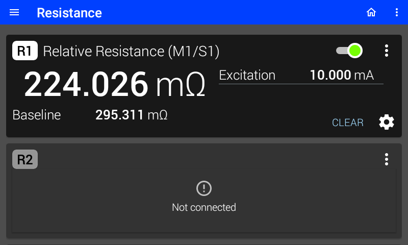
Figure 3.28 Relative DC resistance calculation
AC Excitation type Display Modes
AC Excitation type provides the ability to calculate several unique values related to resistance. The M81-SSM provides three different display modes for AC excitation. These can be selected by tapping the three dots in the upper right-hand corner of the resistance screen:
In-phase and quadrature
Magnitude and phase
Compensated and capacitance
In-phase and Quadrature
The In-phase and quadrature display mode is the default display mode and shows the in-phase and quadrature components of the resistance calculation based on the lock-in’s X and Y measurements. The In-phase component uses the X measurement and the quadrature component uses the Y measurement.
For a setup with a current source module and a voltage measure module, in-phase resistance (\(R_{in-phase}\)) and quadrature resistance (\(R_{quadrature}\)) are calculated as follows:
For a setup with a voltage source module and a current measure module, in-phase resistance (\(R_{in-phase}\)) and quadrature resistance (\(R_{quadrature}\)) are calculated as follows:
Magnitude and Phase
The Magnitude and phase display mode shows the magnitude resistance and phase based on the lock-in’s measurements.
For a setup with a current source module and a voltage measure module, magnitude resistance (\(R_{magnitude}\)) is calculated as follows:
For a setup with a voltage source module and a current measure module, magnitude resistance (\(R_{magnitude}\)) is calculated as follows:
Compensated and Capacitance
The Compensated and capacitance display mode shows a compensated resistance value that is calculated using the lock-in’s magnitude measurement (\(R\)), phase measurement (\(\theta\)), and reference frequency (\(f\)) values. The result is intended to provide a more accurate resistance value for measurements that have errors due to the effect of large parasitic cable and wiring capacitance.
Note
Compensated and Capacitance is only available for the BCS-10 and VM-10 combination.
This can be approximated with the following RC model:
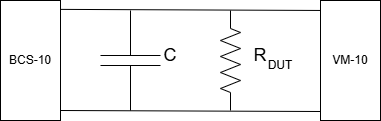
Figure 3.29 Current source, voltage measure RC model
Following the simple RC model above, which is a reasonable approximation of most DUTs when considering parasitic cable capacitance, the current intended to the DUT splits if R, C, or the frequency (f) are large enough to cause a percentage of the current to flow through the capacitor instead of the DUT. When this happens, a phase shift in the DUT lock-in measurement is observed and a smaller than intended current flowing through the DUT causes a smaller voltage measurement than expected. However, by measuring the phase shift across the DUT and knowing the total current output, the DUT resistance measurement can be compensated to be closer to its actual resistance value.
Compensated resistance (\(R_{compensated}\)) and capacitance (\(C\)) are calculated as follows:
Optimization
Optimization controls the overall function of the resistance calculation, introducing resistance ranges. When optimization is enabled, the M81-SSM will change the source amplitude, source range, and measure range according to the specified resistance mode. This limits the source excitation to provide only valid excitation relative to the measure range. When the appropriate resistance range is selected for the application, the instrument will display an accurate resistance calculation.
If optimization is disabled, the instrument no longer displays resistance range or sets the relevant settings. Instead, the source and measure ranges are displayed and can be modified, making it possible to set invalid source values that may overload the sample.
While enabling optimization will automatically update other settings necessary for calculating resistance, it does not prevent these settings from being modified manually. If the resistance source, source amplitude, source range, or measure range are manually changed, the optimization will be disabled by the instrument. None of the other settings will be modified from their present values except the setting that was manually modified.
Optimization also has a “once” command that enables both optimization and autoranging to run once and then disables both settings. After the instrument has configured itself for the best resistance calculation, the relevant measure module’s range will be set to auto. This option requires that the selected source module’s output is enabled before being run. The output will remain enabled after it has completed. The “once” command will disable itself after three resistance settle times have passed without a range change. For more information on the settle time, see the Range section below.
Note
Optimization is not available when two measure modules are being used to calculate resistance.
Optimization Mode
In Lowest noise mode, the source module provides the maximum possible power and therefore the maximum amount of signal. This is the best selection for accuracy and noise of the measurement.
In Lowest power mode, the source module provides low amounts of power. This is the best selection for measurements where self-heating must be kept to a minimum.
Range
Resistance range is available when Optimization is enabled. Each resistance range is tied to a specific source amplitude and measure range. These values are dependant on the resistance mode as well as the type of source module being used for excitation.
Select autorange to allow the M81-SSM to select the best range for the application. When enabled, autoranging will begin with the range that outputs the lowest amplitude based on the following tables.
The instrument will settle for 0.5 s by default
Observation time will be used if enabled.
Settling time will pause until the measure module is settled.
Disabling Optimization will disable autoranging.
Low Noise |
Low Power |
|||
|---|---|---|---|---|
Resistance range |
Source amplitude |
Measure range |
Source amplitude |
Measure range |
1 mΩ |
100 μV |
100 mA |
100 μV |
100 mA |
10 mΩ |
1 mV |
100 mA |
316 μV |
31.6 mA |
100 mΩ |
10 mV |
100 mA |
1 mV |
10 mA |
1 Ω |
100 mV |
100 mA |
3.16 mV |
3.16 mA |
10 Ω |
1 V |
100 mA |
10 mV |
1 mA |
100 Ω |
10 V |
100 mA |
31.6 mV |
316 μA |
1 kΩ |
10 V |
10 mA |
100 mV |
100 μA |
10 kΩ |
10 V |
1 mA |
316 mV |
31.6 μA |
100 kΩ |
10 V |
100 μA |
1 V |
10 μA |
1 MΩ |
10 V |
10 μA |
3.16 V |
3.16 μA |
10 MΩ |
10 V |
1 μA |
10 V |
1 μA |
100 MΩ |
10 V |
100 nA |
10 V |
100 nA |
1 GΩ |
10 V |
10 nA |
10 V |
10 nA |
Low Noise |
Low Power |
|||
|---|---|---|---|---|
Resistance range |
Source amplitude |
Measure range |
Source amplitude |
Measure range |
1 mΩ |
100 mA |
100 μV |
100 mA |
100 μV |
10 mΩ |
100 mA |
1 mV |
31.6 mA |
316 μV |
100 mΩ |
100 mA |
10 mV |
10 mA |
1 mV |
1 Ω |
100 mA |
100 mV |
3.16 mA |
3.16 mV |
10 Ω |
100 mA |
1 V |
1 mA |
10 mV |
100 Ω |
100 mA |
10 V |
316 μA |
31.6 mV |
1 kΩ |
10 mA |
10 V |
100 μA |
100 mV |
10 kΩ |
1 mA |
10 V |
31.6 μA |
316 mV |
100 kΩ |
100 μA |
10 V |
10 μA |
1 V |
1 MΩ |
10 μA |
10 V |
3.16 μA |
3.16 V |
10 MΩ |
1 μA |
10 V |
1 μA |
10 V |
100 MΩ |
100 nA |
10 V |
100 nA |
10 V |
1 GΩ |
10 nA |
10 V |
10 nA |
10 V |
Observation Time
In AC mode, observation time is a simplification of lock-in parameters for resistance calculations. The requested observation time is used to calculate a hybrid filter of the averaging (FIR) and traditional low-pass filter (IIR) filters that focuses on optimizing the equivalent noise bandwidth. This calculation is reliant on the reference frequency of the selected source module.
Note
The observation time may not be exactly the same value as requested. The actual observation time can be located in the info circle on the Observation Time setting. Observation time ranges from 100 ms to 10 s.
When observation time is enabled the requested observation time is used to calculate and apply both the reference (FIR) cycles and IIR time constant settings. Both values are automatically applied and enabled, and a roll-off value of 12 dB is applied.
When observation time is disabled the requested observation time can be changed, but the calculated FIR cycles and IIR time constant are not applied. The tentative values are displayed in the info circle on the Observation time setting, but will not be applied until the observation time is enabled.
In either AC or DC mode, while enabling observation time will automatically update other settings necessary for calculating resistance, it does not prevent these settings from being modified manually. If the settings are manually changed the observation time will be disabled by the instrument automatically. The values will remain the same.
Calculated Resistance Example
The following example illustrates how to configure resistance settings between the first source channel and the first measure channel.
Set the resistance source to S1 and the excitation type to DC.
CALCulate:SENSe1:RESistance:SOURce S1
CALCulate:SENSe1:RESistance:ETYPe DC
Enable optimization, set the mode to NOISE and the range to 10 Ω
CALCulate:SENSe1:RESistance:OPTimize 1
CALCulate:SENSe1:RESistance:MODE NOISE
CALCulate:SENSe1:RESistance:RANGe 10