4.9. System Settings
The settings screen contains various settings and information that aren’t specific to temperature inputs or outputs. Settings located here include, but are not limited to, Relays, Connectivity, Updates, and Reset. To navigate here, tap the Settings button located on the Navigation panel. The following screen will appear.
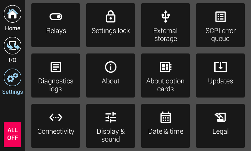
Figure 4.17 Model 346 Settings screen
Note
Firmware updates are discussed in the Service section.
Settings lock is discussed in the Operation section.
Relays are discussed in this Advanced operation section.
About
The About screen provides manufacturing information about the Model 346.
Field |
Description |
|---|---|
Model number |
This field will always display 346. |
Product name |
This field will always display 346 Cryogenic Temperature Controller. |
Serial number |
The unique identifier for this specific 346, assigned during manufacturing. |
Firmware version |
The semantic version number assigned to the Lake Shore Firmware (LSFW) package presently running. |
Calibration date |
The date and time the 346 was last calibrated successfully at Lake Shore. |
Calibration temperature |
The ambient temperature the 346 was calibrated in at Lake Shore. This temperature is relevant when consuming the 1 year accuracy specifications for the 346. |
About option cards
This screen displays information about the input option cards installed in slots E to H. If no card is installed, None will be displayed. If a card is installed, the cards Serial number, Calibration state, and Calibration date will be displayed.
Connectivity
The following fields are displayed on the Connectivity tab. More information about setting up Ethernet can be found in the remote operation section.
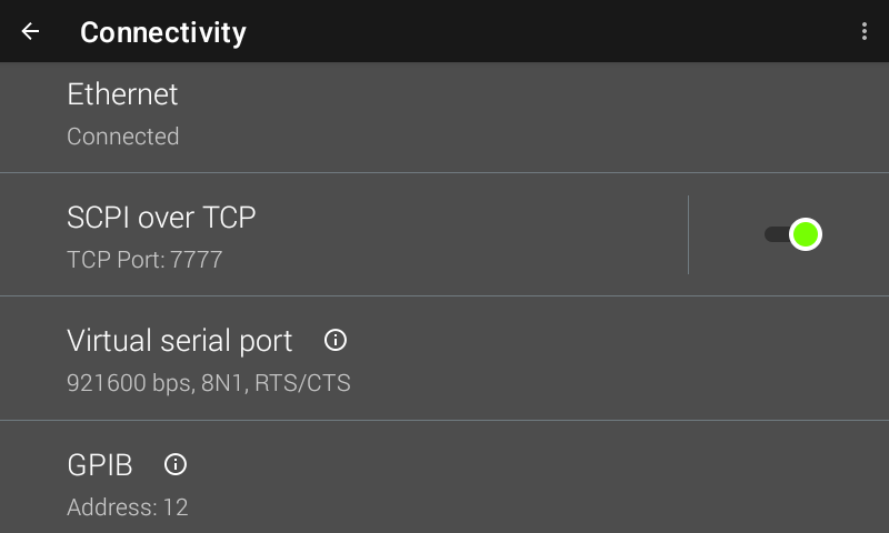
Figure 4.18 Connectivity screen
Field |
Description |
|---|---|
Ethernet |
Touch the Ethernet box to see IP settings. |
SCPI over TCP |
Determines whether the 346 will respond to SCPI commands from the Ethernet connection. Must be enabled to communicate over Ethernet. When disabled, the 346 will not accept connection requests from clients. |
Virtual serial port |
Reports the non-settable configuration of the serial port. See the Remote Operation section for more information. |
GPIB |
Allows setting the GPIB address if the GPIB option card is installed. |
Display & sound
The front panel display brightness can be adjusted for optimal viewing. The default value should work well in most standard room temperature environments, but deviations in room temperature and extreme viewing angles can cause the display brightness to require adjustment for optimal viewing.
As with many touchscreen LED backlit displays, keeping the brightness to a minimum will help to maximize the life of the display. The half-life of the display is rated with a typical value of 30,000 hours. In addition, to help further maximize the life of the display, the Model 346 implements an auto dimming function when the display has not been touched for a prolonged period of time.
The Model 346 will produce sounds on various presses of the screen as a means to provide feedback to the user that a key press has occurred. The volume setting can be set to 100%, 75%, 50%, 25%, or off.
Alarms have their own volume control. The Alarm volume setting can be set to 100%, 75%, 50%, 25% or Quietest.
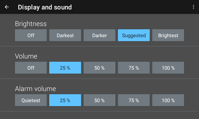
Figure 4.19 Display & sound screen
Legal
This screen is available for the user to see the various open source software used.
Date & time
The Model 346 contains a real-time clock, allowing the current date, time, and time zone to be stored. The time, date and time zone can be set and viewed via the front panel or over the remote interface.
In addition, the Model 346 has a feature to automatically set its date and time with a network connection.
Interface Commands:SYSTem:DATESYSTem:AUTODATETIMESYSTem:TIMESYSTem:TZONE
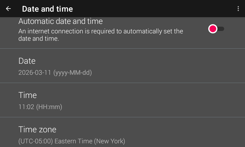
Figure 4.20 Date & time screen
Reset
The Model 346 has two types of settings: instrumentation and system. Instrumentation settings includes settings that are unique to the instrument, such as sensor type, output mode, PID, and ramp rate. System settings are settings common to most instruments, such as volume, brightness and TCP/IP settings. Both types of settings are stored in nonvolatile memory and can be reset to defaults.
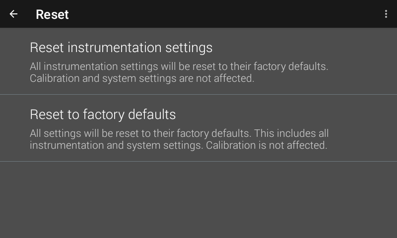
Figure 4.21 Reset screen
Reset instrumentation settings
Instrumentation settings are stored in non-volatile memory. Tap Reset instrumentation settings to reset the Model 346 to the following default settings:
Input Setup—General |
Default |
|---|---|
Sensor type |
Diode |
Filter |
Off |
Input name |
Input A (B, C, D) |
Temperature limit |
0 K (Off) |
Input units |
Kelvin |
Curve |
None |
Input Setup—Diode |
Default |
|---|---|
Range |
2.5 V (Silicon) |
Diode current |
10 μA |
Input Setup—Platinum/NTC RTD |
Default |
|---|---|
Autorange |
On |
Current reversal |
On |
Output Setup |
Default |
|---|---|
Output mode |
Off |
Control input |
Input A for Output 1; Input B for Output 2; C1 for Output 3; D1 for Output 4; None for Outputs 5 to 8 |
Heater resistance |
25 Ω |
Power up enable |
Off |
Output units |
Power (W) |
Max output |
100 W |
Alarm |
Default |
|---|---|
Alarm |
Off |
Relay |
Default |
|---|---|
Relay |
Off |
PID/Manual Heater Power (MHP) Output |
Default |
|---|---|
Proportional (P) |
50.0 |
Integral (I) |
20.0 |
Derivative (D) |
0.0 |
Manual Output |
0.000% |
Heater |
Default |
|---|---|
Heater range |
Off |
Autorange |
On |
Setpoint |
Default |
|---|---|
Setpoint value |
0.000 K |
Zone Settings—All Zones |
Default |
|---|---|
Upper boundary |
0.000 K |
Proportional (P) |
50.0 |
Integral (I) |
20.0 |
Derivative (D) |
0.00 |
Manual output |
0.000% |
Range |
Off |
Ramp rate |
0.000 K/min |
Control input |
Default |
Output limit |
100.000% |
Reset to factory defaults
If necessary, the Model 346 instrument settings can be restored to factory defaults. System settings are stored in non-volatile memory. A factory default reset will reset both instrumentation settings and system settings. As with the reset instrumentation settings function, a factory default will not affect calibration. In addition, user curves will not be cleared.
When a factory reset in initiated, diagnostic logs and user added firmware repositories are cleared (the default firmware.lakeshore.com/production remains). In addition, the following system settings are reset back to their default state:
Connectivity—general |
Default |
|---|---|
SCPI over TCP |
Disabled |
TCP socket port number |
7777 |
Connectivity—Ethernet |
Default |
|---|---|
IP Configuration |
DHCP |
Static IP |
192.168.0.12 |
Static Gateway |
192.168.0.255 |
Static Subnet mask |
255.255.255.0 |
DNS 1 |
8.8.8.8 |
DNS 2 |
8.8.4.4 |
Connectivity—GPIB |
Default |
|---|---|
Address |
12 |
Display and sound |
Default |
|---|---|
Brightness |
Suggested |
Volume |
50 |
Alarm volume |
50 |
Date and time |
Default |
|---|---|
Automatic date and time |
Disabled |
Time zone |
GMT |