4.7. Alarms
Each input of the Model 346 has high and low alarm capability. Sensor input reading data can be compared to the alarm setpoint values. A reading higher than the High setpoint triggers the high alarm for that input. A reading lower than the Low setpoint triggers the low alarm for that input.
Along with ColdSync™, the Model 346 allows for alarm setup from the front panel. This is done from the input details page, which can be accessed by tapping the input card visible on either the Home screen or the I/O page. The following image shows the alarm settings within the input details page.
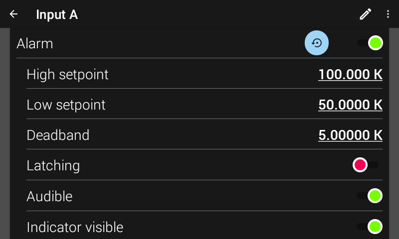
Figure 4.13 Alarm settings screen
The units of High setpoint, Low setpoint, and Deadband are dependent on whether a curve is assigned to the specified input. If a curve is not assigned to the specified input, the settings will be interpreted in sensor units. When a curve is assigned to an input, this causes the Model 346 to interpret the High setpoint, Low setpoint, and Deadband in Temperature units. Temperature units are also configured in the input setup menu.
Interface Command: ALARM
Note
Changing between sensor types, or assigning / removing a curve, will cause these values to return to default to prevent an alarm from going off accidentally.
Alarm Annunciators
If the Audible setting is enabled for an enabled alarm, the beeper inside the instrument will sound when the alarm activates. The Audible setting can also be set to disabled to keep the audible alarm from sounding when an alarm is triggered. The setting for alarm volume is found by tapping Settings on the navigation panel, then Display & Sound, then adjusting alarm volume. When an alarm is triggered and becomes audible, a pop-up will appear on the front screen to quickly allow the user to silence the alarm.
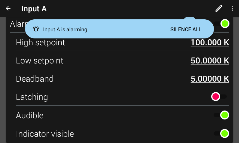
Figure 4.14 Alarm silence pop-up
The alarm indicator is displayed when an alarm is enabled, actively alarming, and has the Indicator Visible setting enabled. If viewing an input card, the indicator will state ALARM. If viewing an input details page, a more specific LOW ALARM or HIGH ALARM indicator will be displayed. You may want to set the Indicator visible setting to disabled if there is no need to show the alarm state on the front panel, for instance, if you are using the alarm function to trigger a relay.
Note
The two relays on the Model 346 can also be tied to alarm functions as described in the Relays section of this manual.
Alarm latching
Latching alarms are often used to detect faults in a system or experiment that requires operator intervention. The alarm state remains visible to the operator for diagnostics even if the alarm condition is removed. When paired with a relay, the relay can signal remote monitors, or for added safety, disable critical equipment.
You can clear a latching alarm by navigating to the Input details page. A pop-up will appear at the bottom of the screen asking if you want to reset all alarm latches. In addition, you can tap the blue Reset all alarm latches button located next to the Alarm enable setting.
Non-latching alarms are often tied to relay operation to control part of a system or experiment. The alarm state follows the reading value. The deadband parameter can prevent relays from turning on and off repeatedly when the sensor input reading is near an alarm setpoint.
The following figure illustrates the interaction between Alarm Setpoint and Deadband in non-latching operation. With the High setpoint at 100 K and the deadband at 5 K, the high alarm triggers when sensor input temperature increases to 100 K, and it will not deactivate until the temperature drops to 95 K. In addition, the same 5 K deadband is applied to the low alarm setpoint as well.
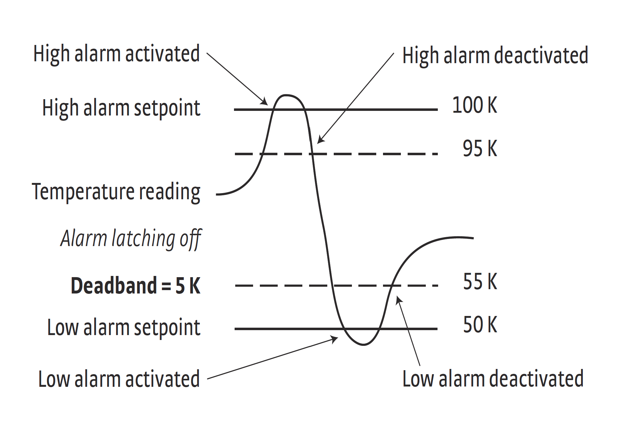
Figure 4.15 Alarm deadband example