6. Options and Accessories
6.1. General
This chapter provides information on the models, options, and accessories available for the Model 346 temperature controller.
6.2. Models
The list of Model 346 model numbers is provided as follows:
Model |
Description of Models |
|---|---|
346 |
Standard temperature controller with 10 diode/RTD inputs and 8 control outputs |
6.3. Options
Model |
Description of Options |
|---|---|
3401 |
4 channel RTD / Diode option card |
3402 |
Dual thermocouple option card |
6.4. Accessories
Accessories are devices that perform a secondary duty as an aid or refinement to the primary unit. Refer to the Lake Shore Temperature Measurement and Control Catalog for details. Please visit shop.lakeshore.com for more information.
Note
CE / NRTL certifications are pending for Model 346 accessories
6.5. Rack Mounting
The Model 346 can be installed into a 483 mm (19 in) rack mount cabinet using the optional Lake Shore Model RM-1 full-rack mount kit. The kit contains the necessary parts to mount the instrument into a space 483 mm (19 in) wide by 88.9 mm (3.5 in) high. See https://www.lakeshore.com/rack-kit/ for full details.
Note
Ensure that there is a 25 mm (1 in) clearance on both sides of the instrument after rack mounting.
6.6. Input Option Card Installation
The field installable option cards add extended input functionality to inputs E to H. Calibration for the options are stored on the card so you can install it in the field and use it with multiple Model 346 temperature controllers without recalibration.
The Model 346 input option cards are field-installable. You will need a small Phillips head screwdriver. Follow this procedure to install an input option card.
 To avoid potentially lethal shocks, turn off the controller and disconnect it from AC power
before performing these procedures.
To avoid potentially lethal shocks, turn off the controller and disconnect it from AC power
before performing these procedures.
 Pour éviter les chocs potentiellement mortels, éteignez le contrôleur et débranchez-le de
l’alimentation secteur avant d’effectuer ces procédures.
Pour éviter les chocs potentiellement mortels, éteignez le contrôleur et débranchez-le de
l’alimentation secteur avant d’effectuer ces procédures.
 The components on this board are electrostatic discharge sensitive (ESDS) devices.
Follow ESD procedures in the Service section to avoid inducing an electrostatic discharge (ESD)
into the device.
The components on this board are electrostatic discharge sensitive (ESDS) devices.
Follow ESD procedures in the Service section to avoid inducing an electrostatic discharge (ESD)
into the device.
 Les composants de cette carte sont des dispositifs sensibles aux décharges électrostatiques (ESDS).
Suivez les procédures ESD de la section Service pour éviter de provoquer une décharge électrostatique (ESD)
dans l’appareil.
Les composants de cette carte sont des dispositifs sensibles aux décharges électrostatiques (ESDS).
Suivez les procédures ESD de la section Service pour éviter de provoquer une décharge électrostatique (ESD)
dans l’appareil.
Turn off the Model 346 power switch. Unplug the power cord from the wall outlet, then from the instrument.
Using a #1 Phillips screwdriver, remove the screws from the top panel. Remove the top panel
Remove the rear panel cover for the desired option card slot (screws shown in red circles below). Input G is shown in the example below.
Slowly and carefully, insert the option card plus bracket into the rear slot loosely. Ensure not to scrape the main board.
Attach the ribbon cable to the main board (blue arrow).
Orient and secure the option card to the rear panel using the screws from step 3.
Re-install the top cover.
Replace the power cord in the rear of the unit and set the power switch to On.
To verify option card installation, tap I/O from then navigation panel, then navigate to the Input summary page. Scroll down and verify the input cards are displayed for the slot you installed the option card in. For example, if you installed a 3401 card in slot G, verify that cards Input G1, Input G2, Input G3 and Input G4 are displayed.
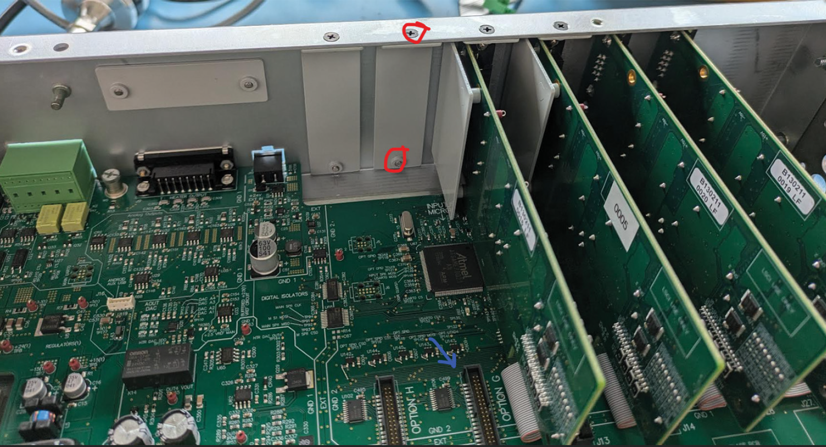
Figure 6.1 Option card slots