2.3. Rear Panel
This section provides a description of the M81-SSM rear panel connections.
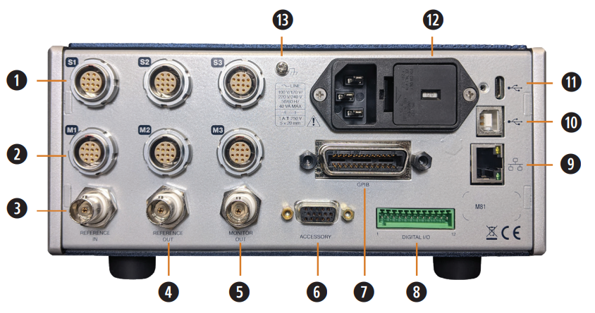
Figure 2.3 M81-SSM rear panel
Source module connectors Connect source modules to these connectors.
Measure module connectors Connect measure modules to these connectors.
Reference in BNC connector Allows connection of an external phase reference. See Reference In.
Reference out BNC connector Provides phase reference to external equipment. See Reference Out.
Monitor out BNC connector Configurable analog output. See Monitor Out.
DB15 accessory connector For future use.
IEEE-488 connector Connects the instrument to a IEEE-488 bus.
Digital I/O This terminal block provides configurable digital inputs and outputs. See Digital I/O.
RJ-45 Ethernet interface The Ethernet interface is provided to allow connection to a computer network.
USB serial communications interface The USB interface is provided to connect with most modern computers.
USB Type-C™ interface Connect to USB devices such as flash drives. Compatible with screw locking connectors.
Line input assembly Power is provided through the line input assembly.
Chassis ground connection Screw for chassis ground connection (M3×6).
See connector definitions for more information on these connectors.
Line Input Assembly
This section describes how to properly connect the M81-SSM to line power. Please follow these instructions carefully to ensure proper operation of the instrument and the safety of operators.
For further instructions, see Fuse and Line Voltage Selection.
Line Voltage
The M81-SSM has four different AC line voltage configurations so that it can be operated from line power anywhere in the world. The nominal voltage and voltage range of each configuration is shown below. (The recommended setting for 230 V operation is 240 V.)
Nominal |
Minimum |
Maximum |
|---|---|---|
100 V |
90 V |
110 V |
120 V |
108 V |
132 V |
220 V |
198 V |
242 V |
240 V |
216 V |
264 V |
Caution
AC line voltage is set at Lake Shore, but it is good to verify that the AC line voltage indicator in the fuse drawer window is appropriate before turning the instrument on. The instrument may be damaged if turned on with the wrong voltage selected.
Line Fuse and Fuse Holder
The line fuse is an important safety feature of the M81-SSM. If a fuse ever fails, it is important to replace it with the value and type indicated on the rear panel for the line voltage setting. The letter T on the fuse rating indicates that the instrument requires a time-delay or slow-blow fuse.
Fuse |
1.6 A T 250 V |
Power Cord
The M81-SSM includes a 3-conductor power cord that mates with the IEC 320-C14 line cord receptacle. Line voltage is present on the two outside conductors and the center conductor is a safety ground. The safety ground attaches to the instrument chassis and protects the user in case of a component failure. A CE approved power cord is included with instruments shipped to Europe; a domestic power cord is included with all other instruments (unless otherwise specified when ordered).
Warning
Always plug the power cord into a properly grounded receptacle to ensure safe instrument operation.
Note
If the power supply cord is damaged or lost, it must be replaced. Contact Lake Shore for a replacement to ensure proper voltage, current and type of cord. The power supply cord must not exceed 3 m (10 ft) in length.
The delicate nature of the measurements being taken with this instrument may necessitate additional grounding including ground strapping of the instrument chassis. In these cases the operator’s safety should remain the highest priority and low impedance from the instrument chassis to safety ground should always be maintained.