7.3. Fuse and Line Voltage Selection
The fuse drawer supplied with the M81-SSM holds the instrument line fuses and line voltage selection module. The drawer holds two 5 mm × 20 mm (0.2 in × 0.79 in) time delay fuses. It requires two good fuses of the same rating to operate safely.
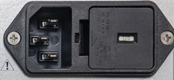
Figure 7.1 Line input assembly
Fuse Replacement
Use this procedure to remove and replace a line fuse.
Warning
To avoid potentially lethal shocks, turn off controller and disconnect it from AC power before performing these procedures.
Caution
For continued protection against fire hazard, replace only with the same fuse type and rating specified for the line voltage selected.
Note
Test fuse with an ohmmeter. Do not rely on visual inspection of fuse.
Locate the line input assembly on the instrument rear panel.
Remove the instrument power cord.
With a small screwdriver, release the drawer holding the line voltage selector and fuse.
Remove existing fuse(s). Replace with proper slow-blow (time-delay) fuse ratings.
Re-assemble the line input assembly in reverse order.
Verify voltage indicator in the line input assembly window.
Connect the instrument power cord.
Line Voltage Selection
Use the following procedure to change the instrument line voltage selector.
Warning
To avoid potentially lethal shocks, turn off controller and disconnect it from AC power before performing these procedures.
Identify the line input assembly on the instrument rear panel.
Remove the instrument power cord.
With a small screwdriver, release the drawer holding the line voltage selector and fuse.
Slide out the voltage selector from the drawer.
Rotate the voltage selector until the proper voltage indicator shows through the window.
Re-assemble the line input assembly in the reverse order.
Verify the voltage indicator in the window of the line input assembly.
Connect the instrument power cord.