7.4. Rear Panel Connector Definitions
Digital I/O
This termial block provides configurable digital inputs and outputs. See Digital I/O for more information.
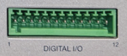
Figure 7.2 Digital I/O connector
Pin |
Description |
|---|---|
1 |
Input 1 |
2 |
I/O ground |
3 |
Input 2 |
4 |
I/O ground |
5 |
+5 V |
6 |
I/O ground |
7 |
Output 1 |
8 |
I/O ground |
9 |
Output 2 |
10 |
I/O ground |
11 |
Measurement ground |
12 |
Earth ground |
The mating connector for the digital I/O is a Phoenix 1923432 terminal block.
USB
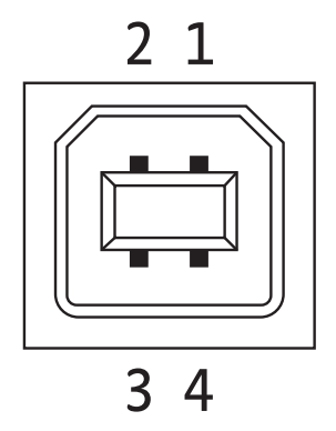
Figure 7.3 USB connector
Pin |
Symbol |
Description |
|---|---|---|
1 |
VCC |
+5 VDC |
2 |
D- |
Data- |
3 |
D+ |
Data+ |
4 |
GND |
Ground |
USB Type-C™
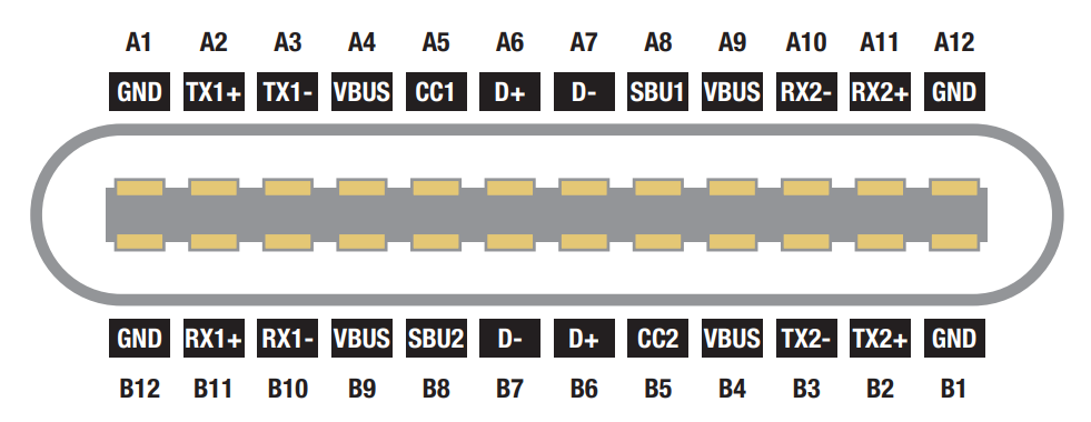
Figure 7.4 USB Type-C™ connector
Ethernet
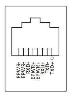
Figure 7.5 Ethernet connector
Pin |
Symbol |
Description |
|---|---|---|
1 |
TXD+ |
Transmit data+ |
2 |
TXD- |
Transmit data- |
3 |
RXD+ |
Receive data+ |
4 |
EPWR+ |
Power from switch+ (not used) |
5 |
EPWR+ |
Power from switch+ (not used) |
6 |
RXD- |
Receive data- |
7 |
EPWR- |
Power from switch- (not used) |
8 |
EPWR- |
Power from switch- (not used) |
Module Connectors
Lake Shore M81-SSM Synchronous Source Measure System source and measure modules plug into these connectors. Source modules must be plugged into “S” ports and measure modules must be plugged into “M” ports.
Connect only Lake Shore M81-SSM Synchronous Source Measure System modules to these connectors.
Ref In
The reference input allows the M81-SSM to track an external phase reference. See Reference In for more information.
BNC pinout:
Center |
Input voltage |
Shell |
I/O ground |
Ref Out
The reference input enables the M81-SSM to provide a phase reference to external equipment. See Reference Out for more information.
BNC pinout:
Center |
Output voltage |
Shell |
I/O ground |
Monitor Out
The monitor output is a configurable analog output. See Monitor Out for more information.
BNC pinout:
Center |
Output voltage |
Shell |
I/O ground |