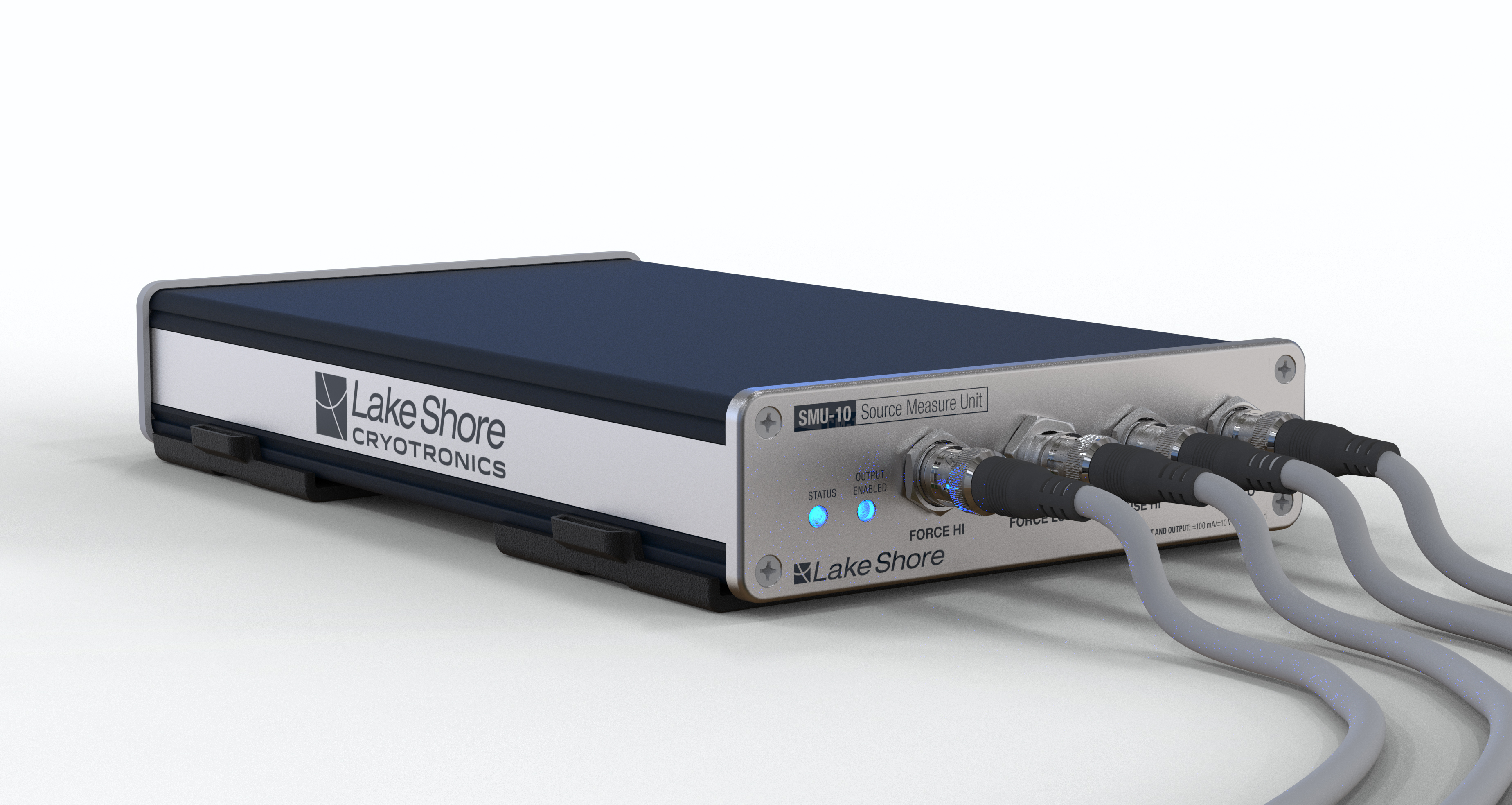
4.1. SMU-10
The SMU-10 is a multifunctional module capable of sourcing either voltage or current while also measuring voltage or current. It is the world’s first lock-in capable SMU.
The SMU-10 supports sourcing and measuring up to 10 V and 100 mA. Full operation requires both source and measure connections to the M81-SSM. These connections must be made on the same channel for a given module. The SMU-10 can operate in source-only mode by connecting and loading only the source connector. In this mode, limited source readback measurement capabilities are available. The source readback monitors the output of the source and supports both DC and AC waveforms, with a maximum frequency of 5 kHz.
The SMU-10 provides:
Configurable voltage source and measure ranges from 10 V to 10 mV
Configurable current source and measure ranges from 1 nA to 100 mA
Configurable high and low voltage and current limits
Configurable local or remote voltage measurement
Configurable local or remote voltage source control
Source output readback measurements
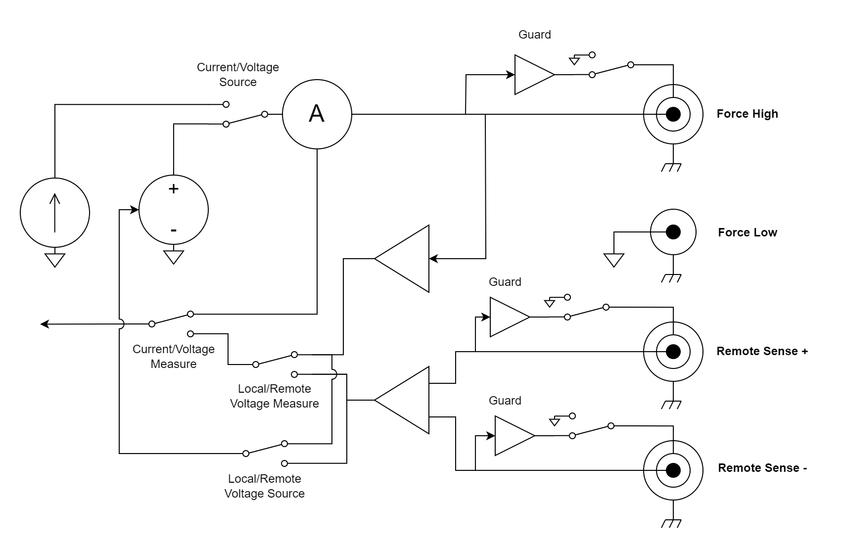
Figure 4.1 Module equivalent diagram
In full operation, the SMU-10 displays the measured value and either the source amplitude or readback measurement. The source amplitude or readback can be configured by pressing the three dots in the upper right corner of the source display area.
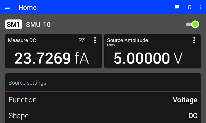
Figure 4.2 SMU-10 settings. Shown with DC current measurement and DC voltage source readback.
In source-only operation, the SMU-10 displays only the source amplitude or readback measurement.
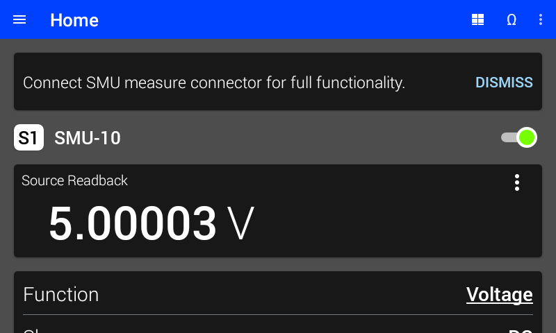
Figure 4.3 SMU-10 source-only operation. Shown with DC voltage source readback.
SMU source settings
Configure the settings for the SMU-10 source on the upper half of the module’s screen:
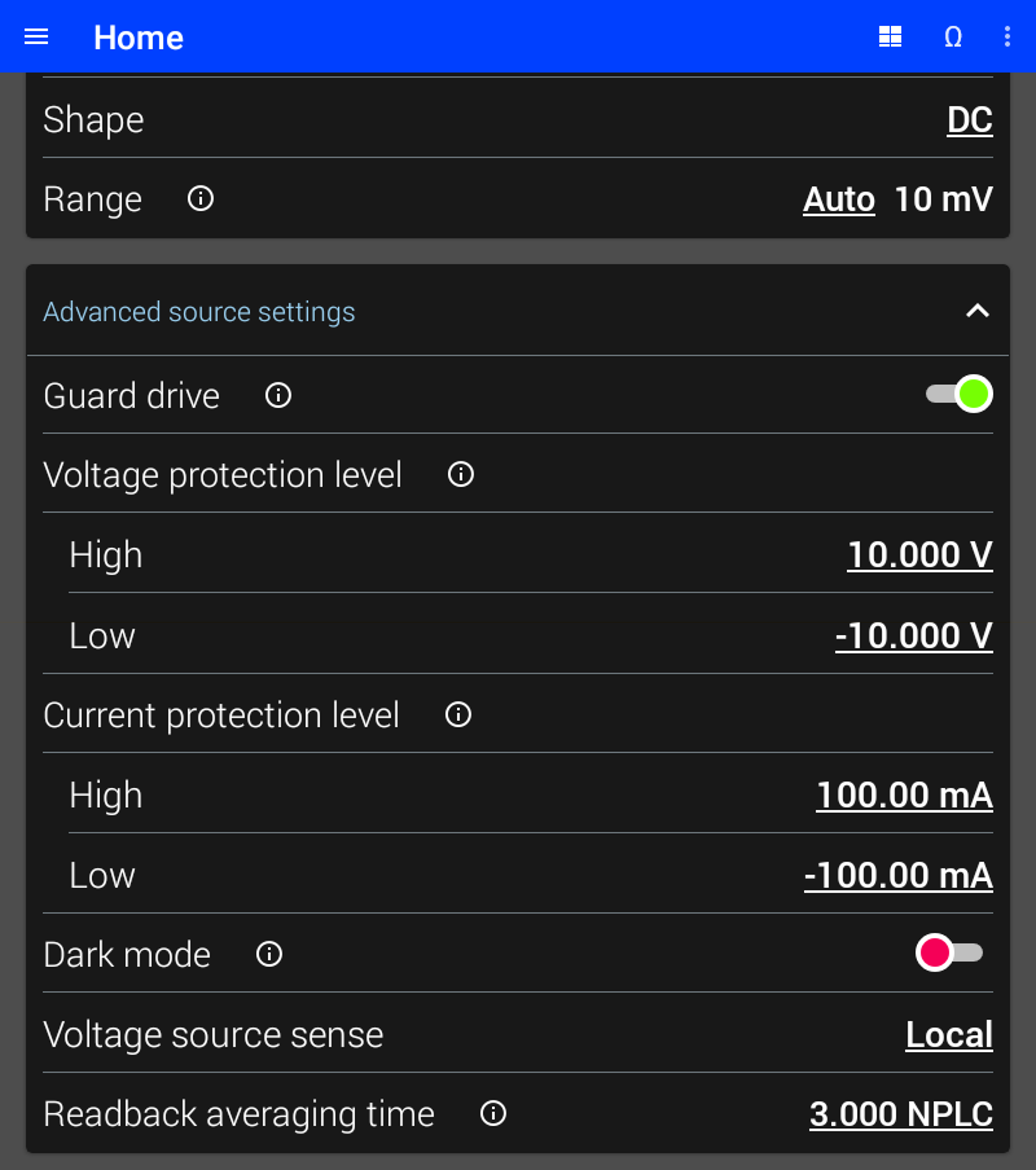
Figure 4.4 SMU-10 DC source settings
Source Function
The SMU-10 can source either voltage or current. The source function configures whether voltage or current is sourced.
Interface Command: SOURce#:FUNCtion:MODE
Source Range
The range determines the largest voltage or current that can be sourced by the module. In general, the lowest range that can be used will provide the best performance. See instrument specifications for the performance characteristics of each range.
If Auto is selected, the M81-SSM selects the lowest voltage or current range that will support the requested amplitude, offset, and frequency each time they are configured.
The available voltage source ranges are 10 V, 1 V, 100 mV, and 10 mV.
The available current source ranges are 100 mA, 10 mA, 1 mA, 100 µA, 10 µA, 1 µA, 100 nA, 10 nA, and 1 nA.
Voltage Source Sense
Voltage source sense configures the SMU-10 voltage source to control either the local or the remote voltage. When Local is selected, the source controls the voltage at the center pin of the Force HI output terminal. When Remote is selected, the source controls the voltage across the remote Sense terminals by adjusting the voltage at the Force HI output terminal. The remote setting only works if an increase in the Force HI output terminal results in an increase in voltage across the remote Sense terminals.
For example, imagine two resistors of equal value are connected in series between the Force HI and Force LO terminals. The remote Sense HI terminal is connected in the middle of these two resistors, while the remote Sense LO terminal is connected to Force LO. A DC source voltage of 1 volt is applied. If the Local voltage sense setting is chosen, the Force HI terminal will be 1 V, while the middle of the resistors will be 0.5 V. If the Remote voltage sense setting is chosen, the Force HI terminal will be 2 V, while the middle of the resistors will be 1 V.
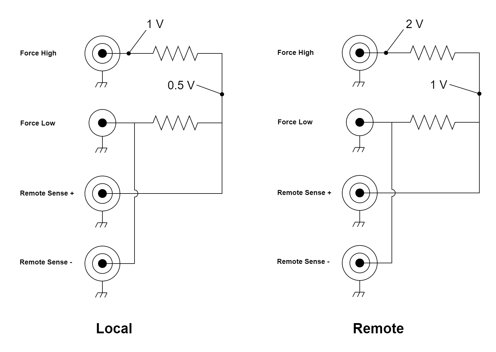
Figure 4.5 Source voltage in Local versus Remote Voltage source sense
Interface Command: SOURce#:VOLTage:SMODe
Guard Drive
If guards are enabled, the inner sheath is driven with the voltage present on the center conductor. The guard minimizes effective capacitance and leakage current. In either setting, the guard should not be connected to ground or to any other low-impedance source.
Each of the three triaxial connectors has its own independent guard drive.
Interface Command: SOURce#:GUARd
Voltage Protection Level
Voltage protection levels can be configured to limit the amount of voltage the SMU-10 will provide and, when sourcing voltage, also limit the maximum programmed voltage (software limit).
When the SMU-10 is sourcing voltage, the voltage protection level acts as a software limit, preventing programmed voltage values above the configured protection level. Any attempt to set a higher voltage will be rejected by the instrument.
When the SMU-10 is sourcing current, the voltage protection level functions as a hardware compliance limit, restricting the maximum output voltage the SMU-10 can deliver while attempting to maintain the programmed current. This is a DC protection behavior and does not limit high‑frequency (>100 Hz) components. When the voltage protection level is reached while sourcing current, the source transitions to a constant‑voltage behavior and remains in that state until the output current is reduced or the load resistance is decreased.
Current Protection Level
Current protection levels can be configured to limit the amount of current the SMU-10 will provide and, when sourcing current, also limit the maximum programmed current (software limit).
When the SMU-10 is sourcing current, the current protection level acts as a software limit, preventing programmed current values from exceeding the configured protection level. The instrument will reject any attempt to set a higher current.
When the SMU-10 is sourcing voltage, the current protection level functions as a hardware compliance limit, restricting the maximum output current the SMU-10 can deliver while attempting to maintain the programmed voltage. This is a DC protection behavior and does not limit high‑frequency (>100 Hz) components. When the current protection level is reached while sourcing voltage, the source transitions to a constant‑current behavior and remains in that state until the output voltage is reduced or the load resistance is increased.
Readback Averaging Time
The SMU-10 measures the actual value of the source output. This is known as the readback. The readback averaging time is specified in number of power line cycles (NPLC). For best rejection of line-related interference, an integer number of NPLC should be selected. The readback measurement can be used to confirm the accuracy of the source or to determine its true value in a limit condition.
Interface Command: SOURce#:READback:NPLCycles
SMU measure settings
Configure the settings for the SMU-10 measure on the lower half of the module’s screen:
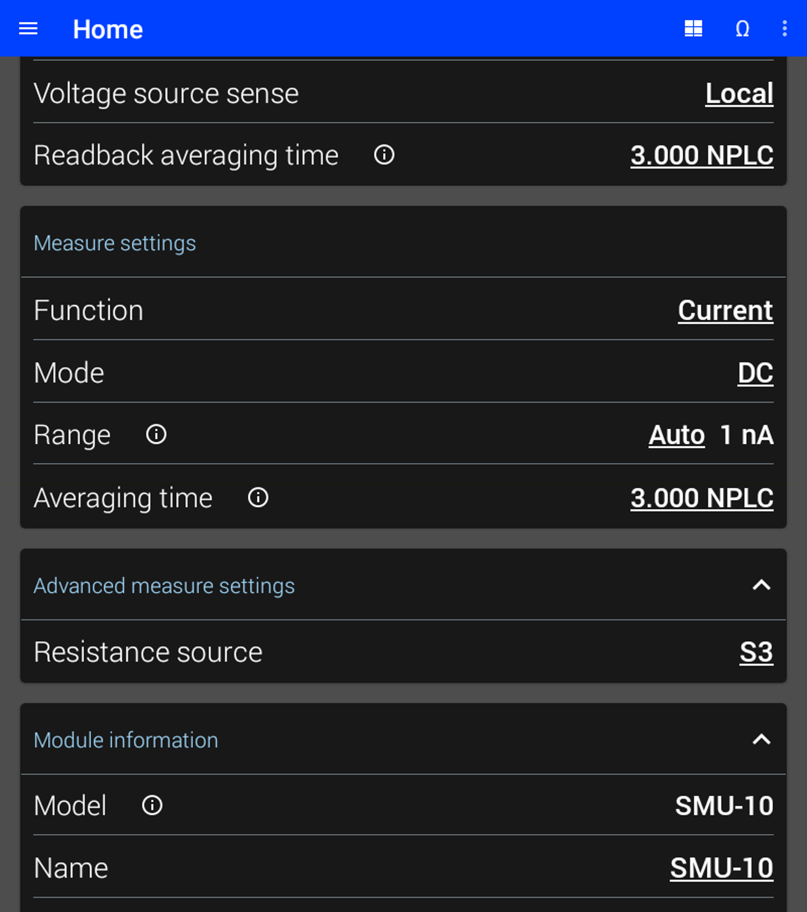
Figure 4.6 SMU-10 DC measure settings
Measure Range
The range determines the largest voltage or current that can be measured by the module. In general, the lowest range that can be used will provide the best performance. See instrument specifications for the performance characteristics of each range.
If auto is selected, the SMU-10 will automatically change ranges based on the input signal. The autoranging algorithm uses the maximum and minimum peak measurements to make decisions. The algorithm will observe the signal over the specified averaging time or time constant before making a decision. Therefore it will take longer to change ranges when the averaging time is longer, for example when there is a large number of NPLCs.
The available voltage measure ranges are 10 V, 1 V, 100 mV, and 10 mV.
The available current measure ranges are 100 mA, 10 mA, 1 mA, 100 µA, 10 µA, 1 µA, 100 nA, 10 nA, and 1 nA.
Measure Function
The SMU-10 can measure either voltage or current. The measure function controls whether voltage or current is measured.
Interface Command: SENSe#:FUNCtion
Voltage Measure Sense
Voltage measure sense configures the SMU-10 to measure either the local or the remote voltage. When Local is selected, the voltage between the Force HI and Force LO terminals is reported. When Remote is selected, the voltage between the remote Sense terminals is reported.
Interface Command: SENSe#:VOLTage:SMODe
Default Settings
The table below lists the settings of the SMU-10 upon initial power on or after settings are reset. For more information about default settings see the Default settings section.
Setting |
Default state |
|---|---|
Function(source) |
Voltage |
Shape |
DC |
Ranging |
Auto, 10 mV |
Amplitude |
0 mV |
Guard drive |
Enabled |
Voltage protection level High |
10 V |
Voltage protection level Low |
-10 V |
Current protection level High |
100 mA |
Current protection level Low |
-100 mA |
Dark mode |
Disabled |
Voltage source sense |
Local |
Readback averaging time |
3.00 NPLC |
Function(measure) |
Current |
Mode |
DC |
Ranging |
Auto, 1 nA |
Averaging time |
3.00 NPLC |
Resistance Source |
S1 |