3.4. Output and Control Setup
Once the sensor inputs have been configured (see Input Setup), the outputs can be configured. This can be done from the output details page, which is accessible from tapping any of the outputs listed under the I/O > Outputs tab. The settings on the output details page are used to create control loops for controlling temperature, whether using feedback (closed loop) or manually setting the output (open loop).
This section describes how to configure and operate the output and control features, and how to set control parameters. Each control parameter should be considered before turning on a control loop output, or the instrument may not be able to perform the most simple control functions. A good starting point is deciding which control loop to use, whether to operate in open or closed control mode, and which tuning mode is best for the application.
To see the control loop on the front panel, assign it to one of the two home screen customizable views. See the Home Screen section under Display Overview for more information.
ColdSync™ software provides a convenient way to setup and configure the outputs of the Model 346. The following image shows the output setup screen in ColdSync™:
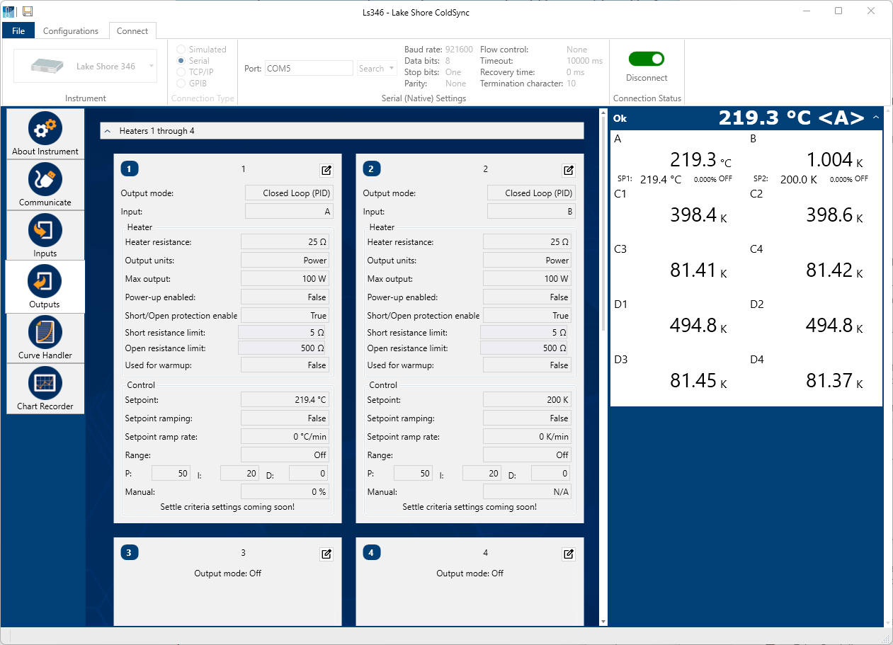
Figure 3.12 ColdSync™ output setup screen
Heater output overview
Heater Outputs 1, 2, 3, and 4 are traditional control loop heater outputs for a cryogenic temperature controller. Each output includes a large set of hardware and software features, making them flexible and easy to use.
The 4 outputs are identical, well-regulated DC current sources, with a maximum current output of 2 A and a nominal compliance voltage limit of 50 VDC. This provides quiet, stable control for a broad range of temperature control systems in a fully integrated package.
For a maximum power output of 100 W, the heaters are optimally designed to drive 25 Ω loads. The heaters have been designed and tested to drive resistive loads ranging from 10 Ω to 100 Ω. Resistive loads outside of that range can be driven within the operating limits of the 2 A/50 V current source, but performance is not guaranteed.
In addition, there are two full-scale power ranges available. The High range is capable of providing up to 100 W (2 A), while the Low range is better suited for low temperature applications, and has a maximum output power of 1 W (200 mA).
Max output and heater resistance
During setup and configuration, the heaters can be configured in terms of output power, or output current. The Heater resistance and Max output parameters work together to limit the maximum available power into the resistive heater. This is useful for preventing heater damage or limiting the maximum heater power into the system. The Max output setting allows for a current or power limit that keeps the output operating within the voltage compliance limit to ensure the best possible resolution.
Default: Heater resistance>25 Ω, Output units>Power (W), Max output>100 WInterface Command: HTRSET
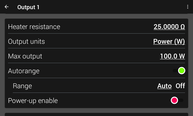
Figure 3.13 Heater setup screen
Note
Max output and Heater resistance work with the heater range setting to provide safety and flexibility.
Output units
The current/power output units settings determines how the output percentage is applied to the heater. When in units of current, the heater output percentage is a percentage of the full-scale current, as specified in the Max output parameter. When in units of power, the output percentage is a percentage of full-scale power, also specified by the Max output parameter.
For example, if the full-scale output is 100 W, units are set to Power, and 50% output is requested, the heater current source will provide 1.41 A to your 25 Ω load for a total of 50 W.
Note
The heater output display is a calculated value intended to aid in system setup and tuning. It is not a measured value, and may not accurately represent actual power in the heater.
Max output
As mentioned before, the Max output setting allows for a current or power limit that keeps the output operating within the voltage compliance limit to ensure the best possible resolution.
It should also be noted that this Max output value is applicable only for the HIGH heater range. If the LOW range is selected, the Model 346 automatically scales down the Max output setting accordingly. For example, in power mode, if the Max output is set to 50 W, then 50 W will be the maximum output (100%) when the HIGH range is selected. When the LOW range is selected, maximum output (100%) will be 500 mW, since the LOW range hardware is designed to output 1/100th of the HIGH range power. The same idea applies to current. If the Max output is set to 1 A, then 1 A will be used for the HIGH range Max output (100%), while 100 mA will be used for the LOW range Max output (100%), since the LOW range hardware is designed to output 1/10th of the HIGH range current.
For use with heater groups (9 and 10), the Max output and Heater resistance parameters are unused, as the physical channels (1 to 4) are used to determine the Max output and Heater resistance of their respective heater loads. Heater groups are discussed in the Advanced Operation section of this manual.
Note
From the front panel, if you attempt to set a Max output that exceeds the current/power hardware limits of the output, based on the Heater resistance, the Model 346 will limit the Max power output accordingly. For example, if the Heater resistance is set to 50 Ω, and you attempt to enter a Max output of 70 W, the Model 346 will limit the Max output to 50 W, as that is the maximum power the 2 A/50 V current source can deliver to a 50 Ω load.
Power-up enable
All heater configuration parameters of the Model 346 can be retained through a power cycle. Some systems require that the Heater Range is turned off when power is restored. The power-up enable feature allows you to choose whether or not the Heater Range is turned off each time the instrument power is cycled. Set the Power-up enable parameter to Off to ensure that the Heater Range is turned off on power up. Set it to On to return the Heater Range to its previous setting when power is restored.
Default: OffInterface Command: OUTMODE
Output modes
The heater outputs can be configured in one of four output modes: Off, Closed loop PID, Zone, or Open loop. The Off mode prevents current from being sourced to the given output. Closed loop PID is the mode most often used for controlling temperature. Zone mode builds on the Closed loop mode by providing automatic changing of control parameters at up to ten different temperature zones. Open loop mode provides a means of applying a constant output.
Default: OffInterface Command: OUTMODE
Closed loop PID mode
The Closed loop PID mode is the most commonly used control mode for tightly controlling temperature using the heater outputs of the Model 346. In this mode the controller attempts to keep the environment at exactly the user-entered setpoint temperature, using feedback from the control input sensor to calculate and actively adjust the control output setting. The Model 346 uses a control algorithm called PID that refers to the three terms used to tune the control. In Closed loop PID mode, the controller will accept user-entered Proportional, Integral, and Derivative parameters to provide 3-term PID control. Manual output can be used during closed loop control to add to the calculated PID control output.
Zone mode
Optimal control parameter values are often different at different temperatures within a system. Once control parameter values have been chosen for each temperature range (or zone), the instrument will update the control settings each time the setpoint crosses into a new zone.
Note
The control parameters can be changed manually. As in Closed loop PID mode, they will be automatically updated once the setpoint crosses a zone boundary
The control algorithm used for each zone is identical to that used in Closed loop PID mode. The Zone feature is useful by itself, but it is even more powerful when used with other features. It is recommended to use zone mode with setpoint ramping. Refer to the Advanced Operation section of this manual for details on setting up zones.
Open loop mode
Open loop output mode allows you to directly set the output using only the Manual output and Range parameters. This guarantees constant output to the load, but it does not actively control temperature.
You can configure any output to Open loop mode. The manual output percentage and the heater range are selectable from the output details page, and more conveniently, when that output is assigned to one of the views on the Home screen.
 Since there is no sensor feedback in Open loop mode, there is nothing to prevent the system
from being overheated. We recommend using the Temperature Limit feature to help
protect the system from overheating.
Since there is no sensor feedback in Open loop mode, there is nothing to prevent the system
from being overheated. We recommend using the Temperature Limit feature to help
protect the system from overheating.
 Puisqu’il n’y a pas de retour de capteur en mode boucle ouverte, rien n’empêche le système
d’être surchauffé. Nous vous recommandons d’utiliser la fonction Limite de température pour vous aider
protéger le système de la surchauffe.
Puisqu’il n’y a pas de retour de capteur en mode boucle ouverte, rien n’empêche le système
d’être surchauffé. Nous vous recommandons d’utiliser la fonction Limite de température pour vous aider
protéger le système de la surchauffe.
Control parameters
Once the output mode is chosen, the control parameters can be used to begin controlling temperature. Control Input is used to create a control loop. The P, I, and D parameters provide fine tuning of the control algorithm. Manual Output provides a baseline output power about which to control. Setpoint is used to set the desired target temperature.
Note
Heater Range is used to turn on the control output and set the power range of the output.
These parameters are described in detail in the following sections.
The most convenient way to set the control parameters is to assign the output to one of the two control loop views on the Home screen. See the view configuration section of Display Overview.
The following image shows the parameters available for use on the control parameters section, located on the bottom left side of the Home screen.
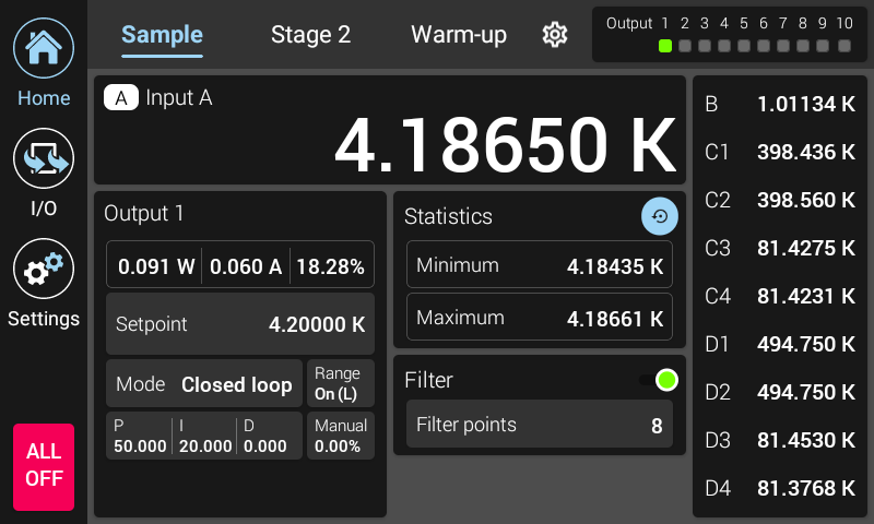
Figure 3.14 Example of control settings available on the home screen
In addition, the control parameters for every output are available within the Output details screen. The Output details screen for a given output can be found by tapping the I/O icon from the navigation panel, then tapping the output summary card for the given output.
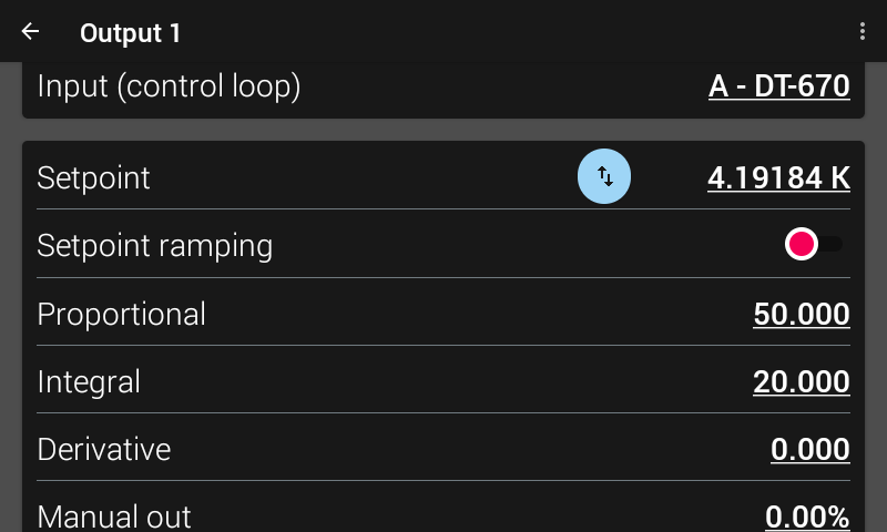
Figure 3.15 Example of control settings available on the output details page
Control loop input
For closed loop control (Closed Loop PID, Zone) a control loop must be created. A control loop consists of a control output for controlling the temperature, and an input for feedback into the control algorithm. On the Output details page, use the Input (control loop) setting to assign the control input sensor to the desired output. In Open loop mode, the Control Input parameter can be set simply for convenience in order to view the input on the Home screen.
Default: Output 1>Input A, Output 2>Input B, Output 3>Input C1, Output 4>Input D1Interface Command: OUTMODE
Proportional (P)
The proportional parameter (also called gain) is the P part of the PID control equation. It has a range of 0 to 100,000. The default value is 50. Enter a value greater than 0 for P when using closed loop control. If proportional is acting alone, with no integral, there will always be some level of error present between the setpoint and the temperature reading.
Default: 50Interface Command: PID
Integral (I)
The integral parameter (also called reset) is the I part of the PID control equation. It has a range of 0 to 100,000. The default value is 20. Setting I to 0 turns the reset function off. The I setting is related to seconds by:
Isetting= 1000 / Iseconds
For example, a reset number setting of 20 corresponds to a time constant of 50 s. A system will normally take several time constants to settle into the setpoint. The 50 s time constant, if correct for the system being controlled, would result in a system that stabilizes at a new setpoint in between 5 min and 10 min.
By adding the integral to proportional contributions, the error that is necessary in a proportional only system can be eliminated. When the error is at 0, controlling at the setpoint, the output is held constant by the integral contribution. The integral setting (I) is more predictable than the gain setting. It is related to the dominant time constant of the load.
Default: 20Interface Command: PID
The P value must be non-zero for the I term to work.
Derivative (D)
By reacting to a fast changing error signal, the derivative can work to boost the output when the setpoint changes quickly, reducing the time it takes for temperature to reach the setpoint. It can also see the error decreasing rapidly when the temperature nears the setpoint and reduce the output for less overshoot. The derivative term can be useful in fast changing systems, but it is often turned off during steady state control because it reacts too strongly to small disturbances. The derivative setting (D) is related to the dominant time constant of the load similar, to the I-setting, and is therefore set relative to I-setting when used.
The derivative time constant should normally be somewhere between p and 1/i the integral time in seconds, if used at all. As a convenience to the operator, the Model 346 derivative time constant is expressed in percent of ¼ the integral time. The range is between 0% and 20,000%. Start with settings of 0%, 50%, or 100%, and determine which setting gives you the type of control you desire. Do not be surprised if the setting you prefer is 0%. Note that by using a percent of integral time, derivative scales automatically with changes in the integral value and does not have to be revisited frequently.
Default: 0%Interface Command: PID
A non-zero value for both P and I must be entered for the D term to work.
Manual output
Manual output is a manual setting of the control output. It can function in two different ways depending on control mode. In open loop control mode, the Manual Output is the only output to the load. You can directly set the control output from the front panel or over the remote interface. In closed loop control mode, Manual output is added directly to the output of the PID control equation. In effect, the control equation operates about the Manual output setting.
The Manual output setting is in percent of full scale. Percent of full scale is defined as percent of full-scale current or power on the selected Heater Range. Available full scale current and power are determined by the Heater resistance, Max output, and Heater Range.
Manual output setting range is 0% to 100%.
Default: 0%Interface Command: MOUT
Setpoint
Use the Setpoint parameter to set the desired load temperature for a control loop. Before entering a setpoint, a control loop must be created by configuring an input sensor and assigning it to a control output using the Control Input parameter. The Setpoint can be entered in either temperature units or sensor units, based on whether a curve is assigned to the input. The Setpoint ramping feature is available when controlling in temperature units to provide smooth, continuous control from one temperature to the next.
Most applications require control in units of temperature. To control in units of temperature, assign a temperature curve to the input, then set the Temperature units parameter of the control input to either kelvin or Celsius. When controlling in temperature, the available setting range of the setpoint is limited by the Setpoint limit parameter, that is specified within the assigned temperature curve.
Note
The Setpoint limit feature only limits the Setpoint entry. For even greater protection, the Temperature limit feature can be used to turn off all heater outputs if a sensor reading above the specified temperature is observed.
There are some instances when temperature control in sensor units may be desired, for example when a temperature curve is not available. For these applications the Model 346 can control temperature in sensor units. To control in sensor units, ensure a curve is not assigned to the input.
Default: 0.0000 KInterface Command: SETP
Note
Temperature control in sensor units can be unpredictable since most sensors do not have a linear response to temperature, and therefore have can have different sensitivity in different temperature ranges.
Note
When controlling in temperature, setpoint is limited by the control input temperature curve’s Setpoint limit. When controlling in sensor units, setpoint is limited by the limits of the configured control sensor.
Setpoint ramping
The Model 346 can generate a smooth setpoint ramp when the setpoint units are expressed in temperature. You can set a ramp rate in degrees per minute with a range of 0 to 100. Once the ramping feature is turned on, its action is initiated by a setpoint change. When you enter a new setpoint, the instrument changes the setpoint temperature from the old value to the new value at the ramp rate. A positive ramp rate is always entered; it is used by the instrument to ramp either up or down in temperature.
Use the ramping feature to minimize temperature overshoot and undershoot. When ramping is not used, a setpoint change can cause the error used by the PID equation to become very large, which causes the I contribution of the control output equation to become larger the longer the error exists. This will result in a large overshoot or undershoot once the setpoint temperature is reached, since the I contribution will only decrease when the error polarity is reversed. Use a ramp rate that keeps the control output from reaching the extremes of 100% or 0% while ramping for optimal results.
The ramping feature is useful by itself, but it is even more powerful when used with other features. Setpoint ramps are often used with zone control mode. As temperature is ramped through different temperature zones, control parameters are automatically selected for best control. Ramps can be initiated and status read back using a remote interface. During computer-controlled experiments, the instrument generates the setpoint ramp while the computer is busy taking necessary data.
Note
When an incomplete ramp is shut off, the setpoint will remain on the most current setting (the reading will not jump to the end of the ramp).
Note
If the input type or input curve is changed while a ramp is in progress, both ramping and the heater are turned off.
Note
If Ramp is on and the setpoint is set to sensor units, the ramping function will remain on but when another setpoint is entered, the setpoint goes directly to the new setpoint value.
To stop a ramp, either from the output details page, or from the home screen, tap Setpoint, then press Enter on the keypad. This stops the ramp at the current setpoint, but leaves the ramping function activated. To continue the ramp, enter a new setpoint.
Default: OffInterface Command: RAMP
Heater range
The Heater Range setting is used for turning a control output on, as well as setting the output power range for the heater outputs. All eight outputs provide an Off setting for turning the output off. The heater outputs, 1 to 4, provide LOW and HIGH settings and can be explicitly set when autorange is disabled. The high range provides maximum power, and the low range provides 1/100th of the maximum power.
The unpowered analog output voltage sources, 5 to 8, do not have multiple output ranges, only a fixed 0 V to 10 V output. Therefore, they only provide an On range setting for enabling the output.
Default: OffInterface Command: RANGE
The following example is meant to illustrate the behavior of the output when a manual range change occurs. For example, lets say a heater is setup for a max power of 100 W and a 25 Ω load, and is in units of Watts. If you set the manual output to 1% and turn the range to HIGH, the heater will be outputting 1% of 100 W, or 1 W. If you then change the range to LOW, the output will continue to output 1%. However, because the range is LOW range, and LOW is defined as 1/100th of the HIGH range output power, the 1% output is now 1% of 1 W, or 10 mW.
Note
While controlling temperature, the following will cause the heater range to automatically turn off:
Exceeding the Temperature limit setting
Setup changes to the control input
Power loss with Power-up enable feature turned off
Input errors such as T. Over, T. Under, S. Over, and S. Under
Note
Available full scale current and power are determined by the Heater resistance, Max current setting, and Heater Range.
Because it may be more desirable to change range and have the output power or current remain constant, the heater autorange feature is introduced.
Heater autorange
While manually changing the heater range maintains the output percentage, autorange is designed to automatically pick the heater range and maintain output power or current between range changes.
When deciding to range up, if the output percentage goes above 10% of current or 1% of power, the Model 346 will set the range to HIGH. When deciding to range down, if the output percentage drops below 8% of current or .8% of power, the Model 346 will set the range to LOW.
Default: OnInterface Command: HTRAUTO
Note
Over the remote interface, even with auto range set to ON, the RANGE command is still needed to turn the output OFF. If the range is set to LOW or HIGH using the RANGE, and autorange is ON, the Model 346 will pick the appropriate range, based on the output percentage.
Output limit
This feature is designed to limit the output percentage of an output, as an extra layer of protection for the system. As a method to limit power output while using zone commands, or when large setpoint changes occur, the output limit can be set to restrict the maximum percentage of allowed output. This prevents spikes of power that are not desired in low cooling power environments that can occur with large step changes. When the output is limited, a chip is displayed on the front panel, and a bit is set in the OUTST? register.
When a limit is set, any command or control loop that attempts to drive the output will be limited to this percentage.
Default: 100%Interface Command: OUTLIMIT
Note
This setting is only settable over the remote interface.
Manual heater range selection
If manually selecting the Heater Range, this percentage limit is applied to the output, and the output percentage will not go above that limit. This is the case if the control loop is asking for an output percentage higher than the limit in Closed loop mode, or the user manually attempts to output a percentage greater than the specified limit in Open loop mode.
For example, if the limit is set to 30%, and the Model 346 is operating in Closed loop mode, if the control loop algorithm attempts to set the output percentage to anything greater than 30%, the output percentage will remain capped as 30%, and a ‘limited’ indicator will appear on the outputs summary panel.
Autorange selection
If autorange is enabled, the output limit is used to limit output power or current, rather than purely output percentage as a function of range. For example, if Heater autorange is enabled, and the Max output setting is set to 100 W, and the Output limit is set to 50%, then the output will be capped at 50 W out (50% of 100 W). Continuing on with this example, if the Max output is then set to 60 W, and the Output limit is kept at 50%, then the Heater output will be capped at 30 W (50% of 60 W).
Heater limits
The Model 346 includes a feature to detect if the heater outputs are attempting to drive an open or a short load. This is done to notify users that something has likely gone wrong with wiring or the heating element, and that the system may not be operating as expected.
The heater outputs are constantly being monitored. If an open or short is detected continuously for 5 s, the heater will be disabled and a notification will appear on the front screen.
Default: Short Resistance–> 5 Ω, Open Resistance–>500 ΩInterface Command: HTRLIM
Note
This setting is only settable over the remote interface.
Note
The heater must also be outputting at least 10% of full scale to get an accurate reading of the heater load’s resistance. If the output percentage is less than 10%, then the heater limits are not checked nor enforced.
ALL OFF
The ALL OFF button is provided as a means of shutting down all control outputs with one button. It is located on the bottom left side of the front panel.
It is equivalent to setting the Heater Range parameter of all outputs to Off.
Analog outputs
Analog outputs 5 to 8 are variable DC voltage sources that can have a range from 0 V to +10 V. The voltage is generated by a 16-bit D/A converter with resolution of 0.3 mV or 0.003% of full scale. These voltage sources are designed to provide a regulated voltage output across a resistive load, as low as 100 Ω. Because of this, the analog outputs are intended to function as auxiliary low-power heaters, capable of providing at most, 1 W of power, when driving a 100 Ω load.
Similar to Heater outputs 1 to 4, the analog outputs include open-loop and Closed loop modes. However, they cannot be used in Zone mode. The analog outputs features include the power-up enable, and control settings like Setpoint/Setpoint ramping, PID, and manual out.
Default: OffInterface Command: OUTMODE
The analog outputs have a single 0 to 10 V range. Therefore, the outputs can be turned on by setting the range parameter to ON
Default: OffInterface Command: RANGE
In addition, the analog outputs can be configured in Monitor out mode, which provides a voltage proportional to an input temperature reading. This can be used by an external device such as a data logger. More information on Monitor out mode can be found in the advanced operation section of this manual.
Overload protection
Outputs 5 to 8 are DC voltage sources. DC voltage sources can be damaged due to overload conditions. Overloading can occur as a result of having too low of a load resistance applied. Because of this, the Model 346 implements an overload protection feature for outputs 5 to 8. Similar to the open/short detection for outputs 1 to 4, the Model 346 continuously monitors the overload state of the analog outputs. If an overload is detected continuously for 5 s, the output will be disabled, and a notification will appear on the front screen.
Overload conditions are determined in the following ways:
The current that the voltage source is providing, is measured to be equal to, or greater than, approximately 110 mA.
The calculated load resistance, based on the measured current and the voltage setting, is less than approximately 95 Ω.