3.3. Input Setup
The Model 346 supports a variety of temperature sensors manufactured by Lake Shore and other manufacturers. An appropriate sensor type must be selected for each input. If the exact sensor model is not shown, use the following sensor input performance chart to choose an input type with similar range and excitation. For additional details on sensors, refer to the Lake Shore Temperature Measurement and Control Catalog or visit our website at www.lakeshore.com.
Note
Any unused input should be set to disabled.
Sensor type |
Display message |
Input range |
Excitation |
Coefficient |
Curve format |
Lake Shore sensors* |
|---|---|---|---|---|---|---|
Silicon diode |
Diode |
0 V to 2.5 V |
10 μA |
Negative |
V/K |
DT-670 series |
Platinum RTD |
PTC RTD (Platinum) |
0 Ω to 1 kΩ (3 ranges) |
1 mA |
Positive |
Ω/K |
PT-100 series platinum |
Negative temperature coefficient (NTC) RTD |
NTC RTD (Cernox™) |
100 Ω to 100 kΩ (7 Ranges) |
100 nA to 100 μA (decade steps in power, autorange maintains <10 mV) |
Negative |
log Ω/K |
Cernox™, Rox™ |
Thermocouple (option 3402 only) |
Thermocouple |
±50 mV |
NA |
Positive |
mV/K |
Type E (Chromel-Constantan), Type K (Chromel-Alumel) |
ColdSync™ provides a convenient way to setup and configure the inputs of the Model 346. The following image shows the input setup screen in ColdSync™:
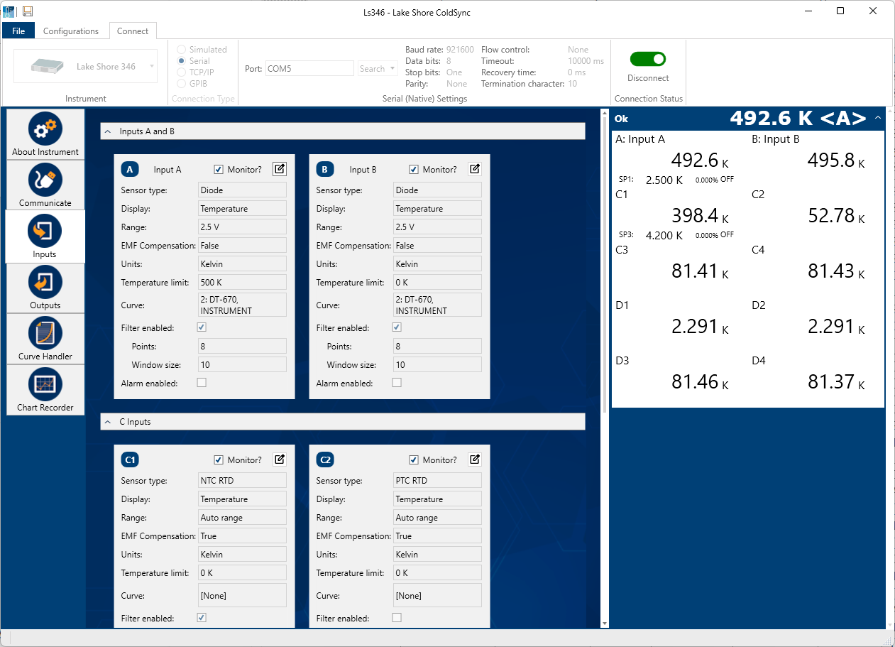
Figure 3.6 ColdSync™ input setup screen
Input sensor type selection
Along with ColdSync™, the Model 346 allows for input setup from the front panel. This is done from the input details page, which can be accessed by tapping the input card visible on either the Home screen or the I/O page. The following image shows the input details page.
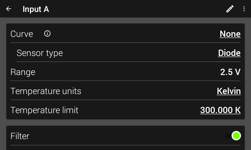
Figure 3.7 Model 346 input details page
The input details page is designed to automatically select the sensor type upon selection of a curve. However, if a curve is not selected, then the Model 346 allows for direct selection of the sensor type.
Available sensor types are Disabled, Diode, PTC RTD (Platinum), and NTC RTD (Cernox™).
Default: DisabledInterface Command: INTYPE
Diode sensor input setup
Diode sensors include the silicon sensors detailed in Table 3.1. The input range is fixed at 0 to 2.5 V, and standard excitation current is 10 μA.
Positive temperature coefficient (PTC) resistor sensor input setup
PTC resistor sensors include the platinum sensor detailed in Table 3.1. The Model 346 supplies a 1 mA excitation current for the PTC resistor sensor type. A resistance range selection is available in order to achieve better reading resolution. By default, autorange is enabled in order to provide the best possible reading resolution, but does not affect the sensor current excitation. Compensation (current reversal) is also enabled by default in order to compensate for thermal EMF voltages.
Negative temperature coefficient (NTC) resistor sensor input setup
NTC resistor sensors include Cernox™, Rox, and others detailed in Table 3.1. The excitation current for the NTC RTD sensor type can vary between 100 nA and 1 mA, depending on resistance range. When autoranging is enabled, the range will be automatically selected so that the excitation voltage is below 10 mV. This keeps the power dissipated in the sensor at a minimum, yet still enough to provide accurate measurements. Compensation (current reversal) is also enabled by default in order to compensate for thermal EMF voltages.
Range selection
The Model 346 is equipped with an autoranging feature that automatically selects the appropriate resistance range for the connected resistive temperature device. In some cases it may be desirable to manually select the resistance range. To manually select a resistance range, select the desired range from the list of available ranges, which de-selects Autorange. By default, Autorange will be On whenever the Sensor type parameter is set to PTC RTD or NTC RTD. Autorange is not available for the Diode sensor type.
Default: OnInterface Command: INTYPE
Table 3.2 Range and sensor power Sensor type
Available range settings
Maximum sensor power
Sensor excitation
Diode
2.5 V (Silicon)
25 μW (at 10 μA excitation)
10 μA
PTC RTD (Platinum)
10 Ω
10 μW
1 mA
100 Ω
100 μW
1 kΩ
1 mW
NTC RTD (Cernox)
100 Ω
1 μW
100 μA
300 Ω
270 nW
30 μA
1 kΩ
100 nW
10 μA
3 kΩ
27 nW
3 μA
10 kΩ
10 nW
1 μA
30 kΩ
2.7 nW
300 nA
100 kΩ
1 nW
100 nA
Thermal electromotive force (EMF) compensation
Sensor excitation is kept low to keep power low, which helps avoid sensor self-heating. There are two major problems that occur when measuring the resulting small DC voltages. The first is external noise entering the measurement through the sensor leads, which is discussed later in this manual with sensor setup. The second is the presence of thermal EMF voltages, or thermocouple voltages, in the lead wiring. Thermal EMF voltages appear when a temperature difference exists between the junction of two dissimilar metals. Thermal EMF voltages must exist because the sensor is almost never the same temperature as the instrument. To minimize them, use careful wiring, make sure the voltage leads are symmetrical in the type of metal used and how they are joined, and keep unnecessary heat sources away from the leads. Even in a well-designed system, thermal EMF voltages can be an appreciable part of a low voltage sensor measurement.
“The Model 346 can help with a thermal compensation algorithm by automatically reversing the polarity of the current source every other reading. The average of the positive and negative sensor readings will cancel the thermal EMF voltage that is present in the same polarity, regardless of current direction. This correction algorithm is enabled by default for RTD sensor types, but can be turned off using the Current Reversal parameter.
The Current Reversal parameter defaults to On any time the Sensor Type parameter is changed to PTC RTD or NTC RTD.
Default: OnInterface Command: INTYPE
Thermocouple sensor input setup (Model 3402 Only)
When a Model 3402 thermocouple option is installed in the Model 346, its two inputs will appear under the Inputs tab in the I/O view, as either Input E, F, G, or H.
Thermocouples include a variety of commercial (such as E, K, T) and specialty types (such as cryogenic Chromel–AuFe). Standard curves are included in the Model 346 for the types listed in Table 3.1. Other types can be used as long as an appropriate temperature response curve is loaded as a user curve. The Model 346 provides one thermocouple range and no excitation because thermocouples do not require it. Room temperature compensation is included for convenience, and should be calibrated before use. Room temperature compensation is enabled by default, but can be turned off if external compensation is being used.
Interface Command: INTYPE
Room temperature compensation
Room-temperature compensation is required to give accurate temperature measurements with thermocouple sensors. It corrects for the temperature difference between the instrument thermal block and the curve normalization temperature of 0 °C. An external ice bath is the most accurate form of compensation, but is often inconvenient. Every thermocouple option card has a temperature sensor integrated into its ceramic thermal block, which allows the instrument to perform internal room-temperature compensation that is adequate for most applications. You can turn room-temperature compensation on or off. The thermocouple option card operates with any thermocouple type that has an appropriate temperature response curve loaded. Room-temperature compensation is not meaningful for sensor units measurements.
Note
Room temperature compensation should be calibrated as part of every installation.
Room temperature compensation calibration procedure
Factory calibration of the instrument is accurate to within approximately ±1 K. Differences in thermocouple wire and installation technique create errors greater than the instrument errors. To achieve the best accuracy, calibrate with the thermocouple actually being used, because it eliminates most sources of error. If that is not possible, use a thermocouple made from the same wire.
Note
It is best practice to use the same material for thermocouple wires; if it is at all possible, it is also best to avoid splices. When splices are necessary, continue the splice with the same type of material.
For less demanding applications, a short across the input terminals will suffice. Both thermocouple inputs should be calibrated, even if they use the same type of thermocouple. An appropriate curve must be selected and room temperature compensation must be turned on before calibration can be started.
The following image shows the room temperature screen, within the thermocouple input details page
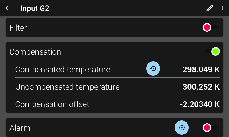
Figure 3.8 Thermocouple compensation screen
Compensated temperature: the “true” user entered temperature when performing the calibration.
Uncompensated temperature: the temperature that the Model 346 reports using just the integrated temperature sensor in the thermal block.
Compensation offset: the difference between the user entered compensated temperature, and the compensated temperature. Strictly for informational purposes.
Follow this procedure to calibrate room temperature compensation:
Note
For best results, the calibration temperature should be close to the measurement temperature that requires best accuracy.
Attach a thermocouple sensor or direct short across the input terminals of the thermocouple input.
Place the instrument away from drafts. If calibrating using a short, place an accurate room-temperature thermometer near the terminal block.
Allow the instrument to warm up for at least 0.5 hr without moving or handling the sensor.
If calibrating with a short, skip to step 6, otherwise insert the thermocouple into the ice-bath, liquid nitrogen, helium dewar, or other known, fixed temperature.
On the thermocouple input details page, read the uncompensated temperature. If the temperature display is not as expected, check to be sure that the thermocouple is making good thermal contact. If possible, add a thermal mass to the end of the thermocouple.
On the thermocouple input details screen, enter the true Compensated temperature that the thermocouple should read. If input is shorted, then enter the actual room temperature measured by the thermometer.
Scroll up to the top of the input details screen to make sure the newly entered Compensated temperature is being displayed.
4-Channel RTD/Diode option card (Model 3401 Only)
When a Model 3401 4-channel RTD/diode option card is installed in the Model 346, 4 additional input channels become available for use. These 4 additional input channels are labeled as Input E, F, G, or H, depending on which input option card slot the Model 3401 is using. For example, if the Model 3401 is installed in input option card slot G, then the input channels would be referred to as G1, G2, G3, and G4. These input channels can be configured for diode, NTC RTD, or PTC RTD sensors, just like the core input channels of A, B, C1 to C4, and D1 to D4.
Default: DisabledInterface Command: INTYPE
Type and range selection
The Model 3401 is equipped with an autoranging feature that will automatically select the appropriate resistance range for the connected resistive temperature device. In some cases it may be desirable to manually select the resistance range. To manually select a resistance range, select the desired range from the list of available ranges, which de-selects Autorange. By default, Autorange will be On whenever the Sensor type parameter is set to PTC RTD or NTC RTD. Autorange is not available for the Diode sensor type.
Available ranges can be seen in Table 3.2.
Reading update rate
The reading update rate for the Model 3401 is dependent on the number of channels enabled. The Model 3401 channels are scanned at a rate of 10 rdg/s (100 ms/rdg).
Number of channels enabled |
Update rate |
|---|---|
1 |
10 rdg/s (100 ms/rdg) |
2 |
5 rdg/s (200 ms/rdg) |
3 |
3.33 rdg/s (300 ms/rdg) |
4 |
2.5 rdg/s (400 ms/rdg) |
Note
Note, the reading rates in Table 3.3 are applicable for inputs C and D as well.
Note
System control performance may be affected by a decreased update rate. Filtering is affected by a decreased update rate.
Temperature curve selection
The Model 346 supports a variety of temperature sensors manufactured by Lake Shore and other manufacturers. Use a curve to convert voltages or resistances to a temperature. The Model 346 can use curves from several sources. Standard curves are preloaded with every instrument and numbered 1 to 20. User curves, numbered 21 to 60, can be used when a sensor does not match a standard curve. The complete list of sensor curves preloaded in the Model 346 is provided in Table 3.4.
Curve number |
Curve name |
Sensor type |
Model number |
Temperature range |
|---|---|---|---|---|
01 |
Reserved |
— |
— |
— |
02 |
DT-670 |
Diode |
DT-670 |
1.4 - 500 K |
03 |
Reserved |
— |
— |
— |
04 |
Reserved |
— |
— |
— |
05 |
Reserved |
— |
— |
— |
06 |
PT-100 |
PTC RTD |
PT-100 |
30 - 800 K |
07 |
Reserved |
— |
— |
— |
08 |
RX-102A-AA |
NTC RTD |
Rox RX-102A |
0.05 - 40 K |
09 |
RX-202A-AA |
NTC RTD |
Rox RX-202A |
0.05 - 40 K |
10 |
RX-103A-AA |
NTC RTD |
Rox RX-103A |
1.4 - 40 K |
11 |
Reserved |
— |
— |
— |
12 |
Type K |
Thermocouple |
Type K |
3 - 1645 K |
13 |
Type E |
Thermocouple |
Type E |
3 - 1274 K |
14-20 |
Reserved |
— |
— |
— |
21-60 |
User Curves |
— |
— |
— |
It is highly recommended to use ColdSync™ software for loading and editing curves from the remote interface. Loading curves with ColdSync™ is discussed in the Advanced Operation section of this manual.
To select a curve from the front panel, navigate to the input details page of the respective input, and tap the Curve setting. The curve selection screen will appear:
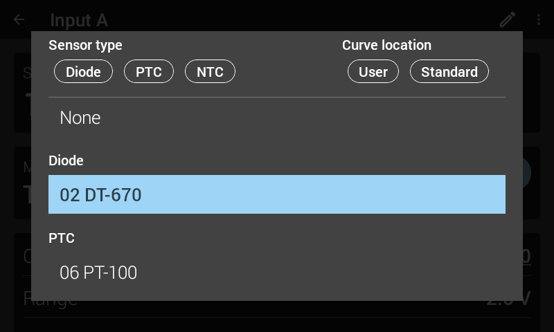
Figure 3.9 Curve selection screen
- The curve selection screen is grouped by Sensor type and Curve location (User or Standard).
Tap the buttons at the top of the screen to filter to certain types of sensors or curves.
Tap the curve you wish to select.
If you decide not to make a selection, scroll to the bottom of the menu and tap OK.
When the curve is set to None, front panel temperature reading fields will display the NO CURVE message, and the interface will report 0 K and –273.15 °C for KRDG and CRDG queries, respectively.
Note
If a curve is not assigned to an input, control and display readings will be in sensor units. When a curve is assigned to an input, control and display readings be in temperature units.
Upon selection of a curve, the Model 346 will automatically select the appropriate sensor type for that curve.
Interface Command: INCRV
Note
On the remote interface, you must first configure the input using the INTYPE command. At that point, a curve that matches the configured sensor type can be assigned to the input using the INCRV command. If the sensor type in the curve header does not match the configured input type, the command is rejected and the curve number returns to 0 (none).
Filter
The reading filter applies exponential smoothing to the sensor input readings. If the filter is turned on for a sensor input, all reading values for that input are filtered. The filter is a running average so it does not change the update rate of an input. Filtered readings are not used for control functions but they are used for all input features including Max/Min.
The number of filter points determines filter bandwidth. One filter point corresponds to one new reading on that input. A larger number of points does more smoothing, but also slows the responsiveness of the temperature reading, relative to real changes in temperature. The default number of filter points is 8, which settles to within six time constants of a step change value in 45 readings, or 4.5 s
The time constant (time it takes to settle to within 36.8% of the step value after a step change) for a given number of filter points can be derived using the following formula: TC = 0.1 / (ln (N / (N - 1)), where TC is one time constant, and N is the number of filter points. A reading is usually considered settled after six time constants. The following table shows a sampling of filter settings and the resulting time constant, settle time, and equivalent noise bandwidth.
Filter points |
Time constant |
Settle time (6 time constants) |
Equivalent noise bandwidth (¼ TC) |
|---|---|---|---|
2 |
0.14 s |
0.9 s |
1.733 Hz |
4 |
0.35 s |
2.1 s |
0.719 Hz |
8 |
0.75 s |
4.5 s |
0.334 Hz |
16 |
1.55 s |
9.3 s |
0.161 Hz |
32 |
3.15 s |
18.9 s |
0.079 Hz |
64 |
6.35 s |
38.1 s |
0.039 Hz |
The filter window is a limit for restarting the filter. If a single reading is different from the filter value by more than the limit, the instrument will assume the change was intentional and restart the filter. The Filter Window is set in percent of full scale range.
When the Model 3401 4-channel RTD/diode option card is installed, the time it takes to get a new reading is increased if more than one scanner channel is enabled. This reduction in update rate modifies the time constant of the filter. The time constant of the filter can be derived using the formula TC = T/(In(N/(N-1)), where TC is one time constant, T is the update rate of the channel in seconds per reading, and N is the number of filter points. Refer to Table 3.3 for information on update rates of the Model 3401. The following table shows a sampling of enabled scanner channels with the number of filter points set to 8 and resulting time constant, settle time, and equivalent noise bandwidth.
Default: Filter–>Disabled, Filter Points–>8, Filter Window–>10% of full scale rangeInterface Command: FILTER
Scanner channels enabled |
Time constant with 8 filter points |
Settle time (6 time constants) |
Equivalent noise bandwidth (¼ TC) |
|---|---|---|---|
1 |
0.75 s |
4.5 s |
0.334 Hz |
2 |
1.50 s |
9 s |
0.167 Hz |
3 |
2.25 s |
13.5 s |
0.111 Hz |
4 |
3.00 s |
18.0 s |
0.083 Hz |
Note
Note, the settle times and ENB in Table 3.6 are applicable for inputs C and D as well.
Input name
To increase usability and reduce confusion, the Model 346 provides a means of assigning a name to each of the sensor inputs. The designated input name is used on the front panel display to indicate which sensor reading is being displayed.
Default: Blank/no-nameInterface Command: INNAME
Note
In a default state, the INNAME query will return a blank string. However, the front panel will display a default name of “Input X”.
To change the input name, navigate to the input details page and tap the pencil icon in the upper right corner of the screen. The following screen will appear:
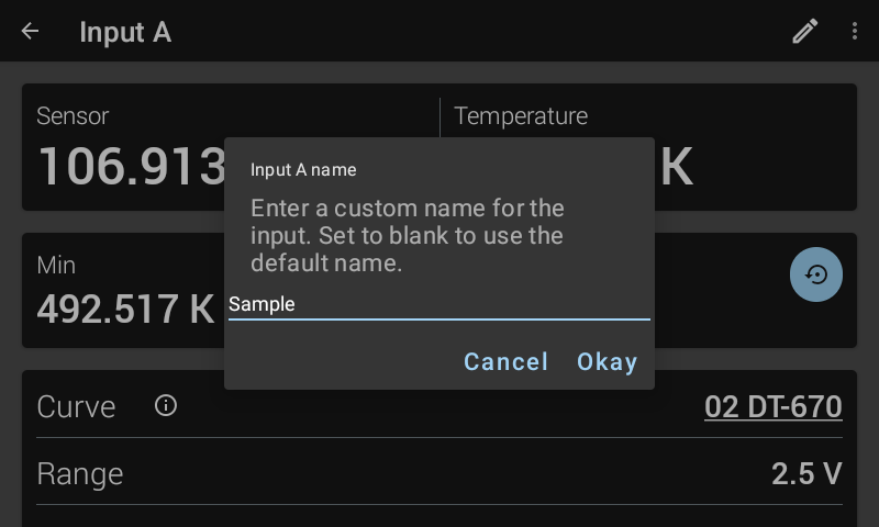
Figure 3.10 Input name screen
Tap the name field and use the keyboard to enter a name for the input.
Tap the checkmark on the bottom right of the keyboard.
Tap Okay.
Note
Names are limited to 32 characters. It is recommended to use only ASCII characters. The keyboard will allow entry of non-ASCII characters, which will display properly on the front panel, but may not be reported properly over the remote interface.
Note
To set the input name to the default state from the front panel, bring up the name entry window, erase the string, and tap Okay.
Temperature limit
The Temperature Limit parameter protects your equipment from damage by shutting down all control outputs when the assigned temperature limit is exceeded on any sensor input. The parameter is available for each of the sensor inputs. A temperature limit of 0 K (default value) turns this feature off.
Default: 0.0000 KInterface Command: TLIMIT
Temperature units
The Temperature units parameter setting determines which units are used to display and/or configure the following:
Temperature reading
Max/Min
Setpoint
Output stability acceptable error
Alarm high and low setpoints, and deadband
Temperature threshold values
High and low values for outputs 5 to 8 when in monitor output mode
Default: KelvinInterface Command: INTYPE
Max/Min
The Max/Min feature captures and stores the highest (Max) and lowest (Min) reading taken since the last reset. If no curve is assigned to the input, the Max/Min readings are in sensor units. If a curve is assigned, then the Max/Min readings are dependent on the temperature units setting.
Minimum and maximum readings are captured continuously. The readings are reset when the instrument is turned off, sensor type is changed, a new curve is assigned to an input, or the Max/Min Reset button is pressed.
Interface Commands: MNMXRST, MDAT?
Over the remote interface, the Max/Min values are reported for every input. On the front panel, they are only visible in the input details screen. Max/Min values are visible for inputs assigned to an output, which can be assigned to one of the views on the home screen.
To reset Max/Min, tap the blue Reset icon, located near the Max/Min readings.
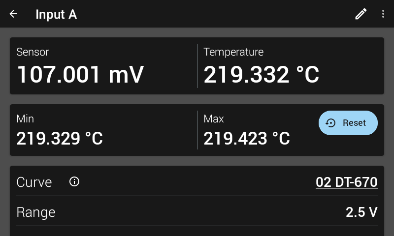
Figure 3.11 Max/Min reset screen