2.5. Thermocouple Sensor Inputs (Model 3402)
The information in this section is for a Model 346 configured with one or more thermocouple sensor inputs. Thermocouple inputs are not installed on the standard Model 346, but can be added by purchasing the Model 3402 dual thermocouple input option card.
Note
Do not leave thermocouple inputs unconnected. Short inputs when not in use.
Sensor Input Terminals
Attach sensor leads to the screws on the off-white ceramic terminal blocks. Sensor connection is important when using thermocouples because the measured signal is small. The block has two thermocouple inputs and each input has two screw terminals; one positive, one negative. See Figure 2.11.
Remove all insulation, then tighten the screws on the thermocouple wires. Keep the ceramic terminal blocks away from heat sources including sunlight and shield them from fans or room drafts.
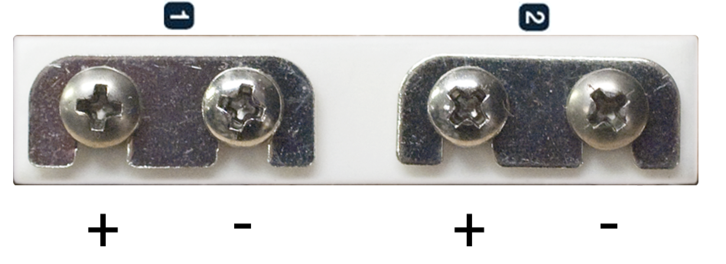
Figure 2.11 Thermocouple input definition and common connector polarities (inputs shown shorted)
Thermocouple Installation
Thermocouples are commonly used in high-temperature applications. Cryogenic use of thermocouples offers some unique challenges.Consider the following when using thermocouples at low temperatures:
Thermocouple wire is generally more thermally conductive than other sensor lead wire. Smaller gauge wire and more thermal anchoring may be needed to prevent leads from heating the sample.
Attaching lead wires and passing them through vacuum tight connectors is often necessary in cryogenic systems. Remember, the thermocouple wire is the sensor; any time it joins or contacts other metal, there is potential for error.
Temperature verification and calibration of room temperature compensation is difficult after the sensor is installed. When possible, keep a piece of scrap wire from each installation for future use.
Thermocouples can be spot-welded to the cryostat for good thermal anchoring as long as the cryostat has a potential close to earth ground.
Grounding and Shielding
Care must be taken to minimize the amount of noise contributed by ground loops when grounding thermocouple inputs. For lowest measurement noise, do not ground thermocouple sensors. The instrument operates with slightly more noise if one of the thermocouples is grounded. Be sure to minimize loop area when grounding both thermocouples. The instrument does not offer a shield connection on the terminal block. Twisting the thermocouple wires helps reject noise. If shielding is necessary, extend the shield from the oven or cryostat to cover the thermocouple wire, but do not attach the shield to the instrument.