2.6. Heater Output setup
The following section covers the heater wiring from the vacuum shroud to the instrument for both heater outputs. Specifications are detailed on the Technical Specifications page at https://www.lakeshore.com/346.
Heater Output Description
Heater outputs 1 to 4 are variable DC current sources used for cryogenic temperature control. Each output supports software-defined ranges and limits, and can be optimized for 25 Ω or a 50 Ω heater resistance. At 50 Ω, output current is limited to 1 A; at 25 Ω, the heater output current is 2 A. The compliance voltage of each output is 50 V minimum, but may reach 53 V if the heater resistance is higher than the nominal setting. Heater power is applied in either high or low range, with each range differing by a factor of 100.
Heater Output Connectors
The main heater outputs use a 15-pin DA-15 style connector. A mating connector (DA-15 plug) is included in the connector kit shipped with the instrument. The connectors included with the instrument were selected for their superior shielding capabilities. If additional connectors are required, purchase them from Lake Shore or search locally for full metal connectors that allow connection to the cable shield. Assembly instructions for the provided connectors are available in the D-sub connector guide.
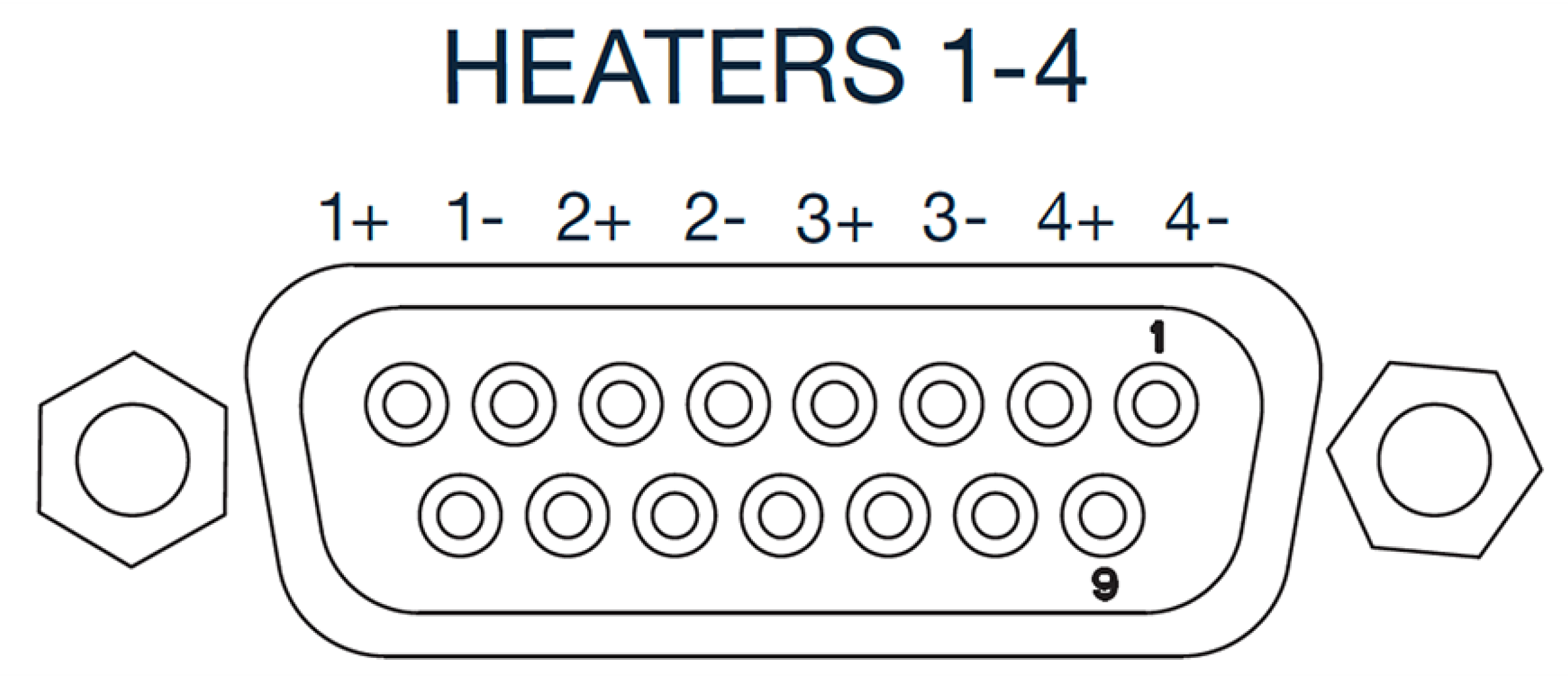
Figure 2.12 Rear panel heater output connector
Pin |
112-415 Cable |
Description |
|---|---|---|
8 |
Orange |
Heater 1 HI |
7 |
White (orange pair) |
Heater 1 LO |
6 |
Red |
Heater 2 HI |
5 |
White (red pair) |
Heater 2 LO |
4 |
Black |
Heater 3 HI |
3 |
White (black pair) |
Heater 3 LO |
2 |
Brown |
Heater 4 HI |
1 |
White (brown pair) |
Heater 4 LO |
10,12,14 |
Additional chassis/earth ground connections |
|
9,11,13,15 |
No connect |
|
Shell |
Shield/drain wire |
Shield |
Heater Output Wiring
Heater output current is what determines the size (gauge) of wire needed to connect the heater. The maximum current that can be sourced from the heaters is 2 A. When less current is needed to power a cooling system, it can be limited with range settings combined with the Max output setting.
When setting up a temperature control system, the lead wire for the heater must be capable of carrying a continuous current that is greater than the maximum current. Wire manufacturers recommend 26 AWG or larger wire to carry 2 A of current.
It is recommended to use twisted heater leads. Large changes in heater current can induce noise in measurement leads and twisting reduces the effect. It is also recommended to run heater leads in a separate cable from the measurement leads to further reduce interaction.
Pre-made cables from Lake Shore are designed to achieve these requirements (part numbers 112-415-03, 112-415-06, and 112-415-10). Wire color information for these cables is included in Table 2.2.
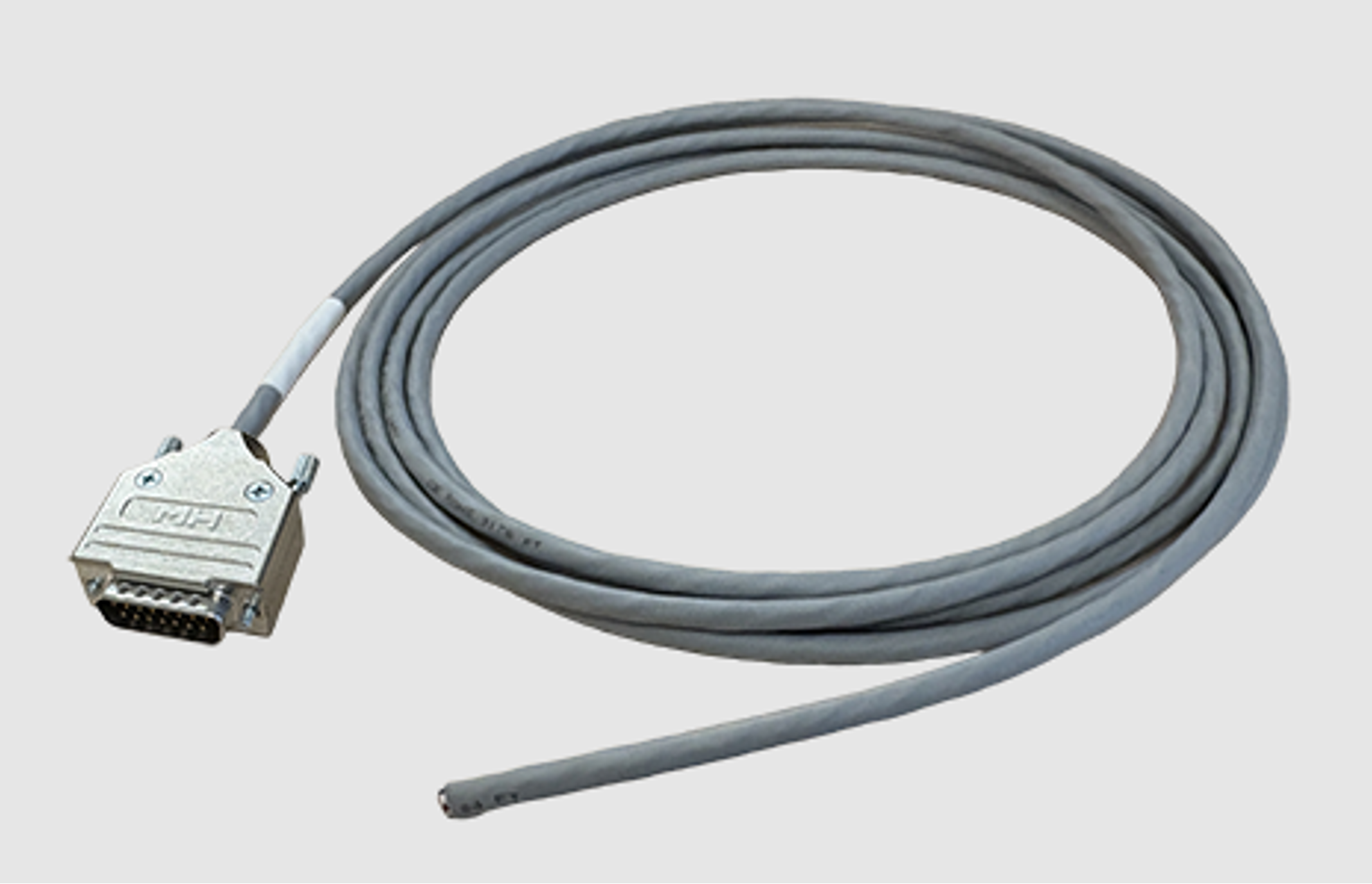
Figure 2.13 Pre-made cable assembly example (112-415-03 heater cable, 3m)
It is recommended to attach the cable shield to the backshell of the DA-15 connector. The pre-made cables provided by Lake Shore meet this recommendation.
In addition, there is a chassis ground screw at the rear panel of the instrument for shielding the heater cable if necessary. The cable shield can be tied to this point using a 3.18 mm (#4) spade terminal, or ring connector.
Note
The shield should never be tied to the heater output leads.
Note
For best noise performance, do not connect the resistive heater or its leads to ground. Also avoid connecting heater leads to sensor leads or any other instrument inputs or outputs.
Heater Output Noise
The heater output circuitry in the Model 346 is capable of sourcing 100 W of power. This type of circuitry can generate some electrical noise. The Model 346 was designed to generate as little noise as possible, but even noise that is a small percentage of the output voltage or current can be too much when sensitive measurements are being made near by.
Powering Outputs 5 to 8 Using an External Power Supply
Outputs 5 to 8 are unipolar, DC voltage sources, and can power heaters directly. However, they are limited to 1 W output (10 V at 100 mA). In addition, these outputs can also be used to program an external power supply, which powers a heater. This section describes choosing and installing an external supply.
Choosing an External Power Supply
Voltage Programmable: the external power supply must be voltage programmable so that Outputs 5 to 8 can control it. Ideally the supply’s programming input should have a range of 0 to 10 V that corresponds to 0 to 10 V range of the control output. This guarantees that 0 to 100% of the control output scales to 0 to 100% power out of the supply. Supplies with different programming input ranges can be used as described below.
DC Output Capable: the external power supply must be capable of continuous DC output. Most commercial audio amplifiers are not suitable because they are AC coupled and cannot provide a DC output.
Output Type: most available voltage programmable power supplies are configured for voltage output. This is different than Outputs 1 to 4 on the 346 which are configured for current output.
Output Voltage: Lake Shore recommends supplies with a working output voltage between 10 V and 50 V. Voltage higher than 50 V poses a shock hazard and should only be used if operator safety can be assured by the installer. Voltage lower than 10 V becomes impractical because the current necessary provide any meaningful power is too high for most cryogenic wiring.
Output Power: there is no limit to the maximum power of the external power supply. Typical warm up applications normally range between 25 W and 200 W.
External Power Supply Setup
Follow all operation and safety instruction in the external power supply manual during setup. Consider the following suggestions for protecting the external power supply and heater load.
Short circuits are common in cryogenic lead wiring. If the external power supply does not specify that it is short circuit protected the power output should be wired with a fuse in series to prevent damage.
Unipolar power supplies are designed to use a positive programming voltage and some can be damaged if the programming voltage is negative. Be careful when wiring the system to maintain the correct polarity.
Some external power supplies can be damaged if there is a programming voltage present at their input when they are turned off. This can happen if the Model 346 and the external power supply use a different source of line power or are turned on and off individually. It can be avoided if the two instruments share a switched power strip.
The heater and wiring in the system must be rated for both the maximum current and maximum voltage provided by the external power supply. The Model 346 can be set to warm up using less than full power if the load will not tolerate the full power of the external power supply.
Connecting to the Model 346
Connect the voltage programming cable (not provided) to the removable terminal block on the rear panel of the Model 346 (see figure below). Output number and polarity of the output leads are indicated on the rear panel. The negative (–) terminals are connected internally to the instrument chassis to provide a ground reference.
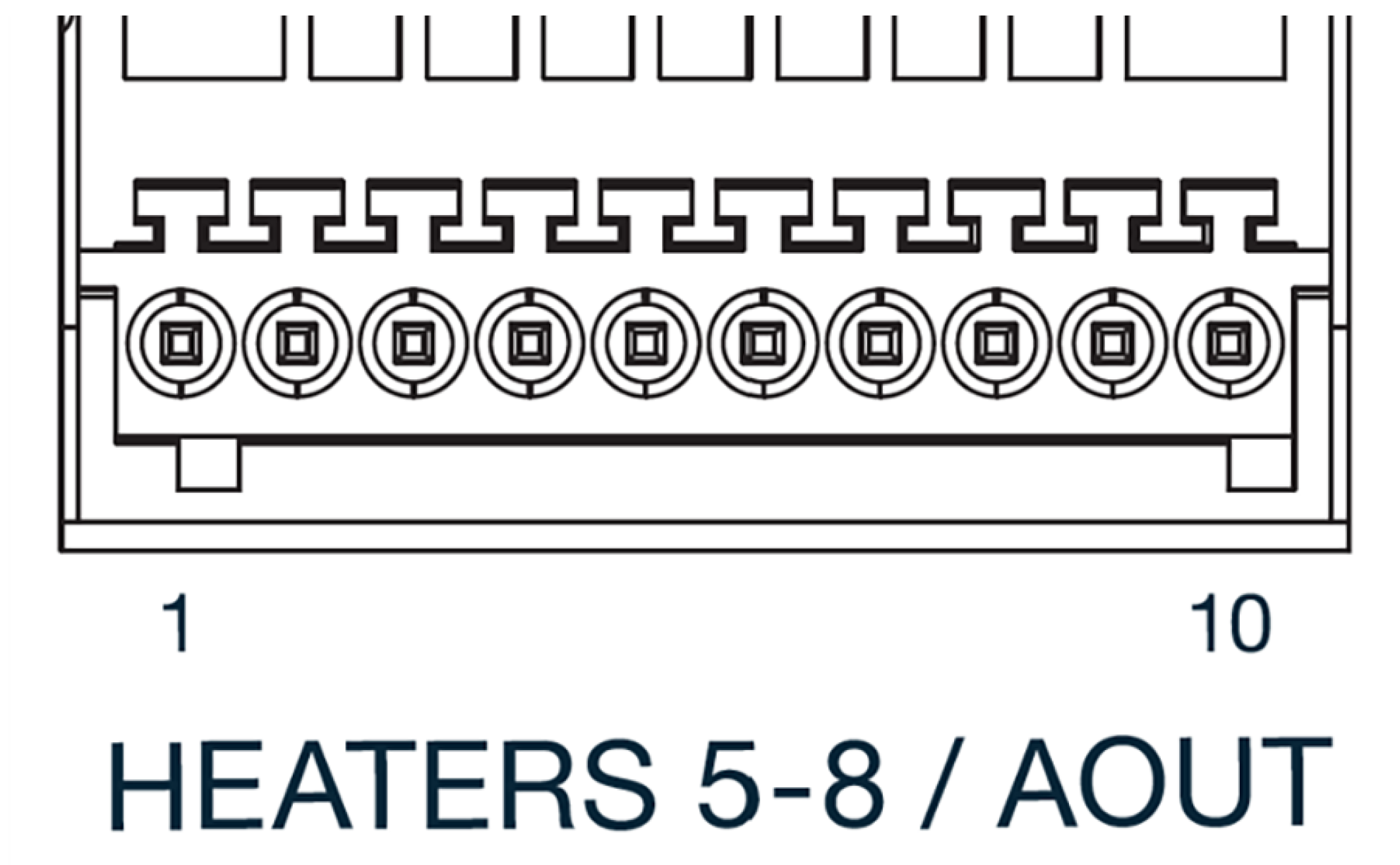
Figure 2.14 Rear panel showing outputs 5 to 8 connector
In the most basic configuration, connect a two-conductor cable directly from the output terminals to the external power supply programming input. Copper wire size 20 AWG to 26 AWG is recommended.
Pin |
Description |
|---|---|
1 |
Output 5 + |
2 |
Output 5 - |
3 |
Output 6 + |
4 |
Output 6 - |
5 |
Output 7 + |
6 |
Output 7 - |
7 |
Output 8 + |
8 |
Output 8 - |
9 |
+5 V isolated supply |
10 |
+5 V isolated supply return |
Programming Voltages Under 10 V
To ensure full output resolution, and protection against overloading the external supply programming inputs, a voltage divider, shown in the following figure, can be used to reduce the control output voltage if the programming input of the external power supply has a range of less than 0 V to 10 V.
The output voltage is proportional to the ratio of resistors R1 to R2: Vout = 10 V × R1/(R1+R2). It is also important to keep the sum of R1 + R2 > 1000 Ω or the Model 346 output may not reach the output voltage setting due to internal overload protection.
For a programming input range of 0 V to 5 V, recommended values are: R1 = R2 = 2000 Ω.
For a programming input range of 0 V to 1 V, recommended values are: R1 = 500 Ω, R2 = 4500 Ω.
Exact resistor value, type and tolerance are generally not important for this application.
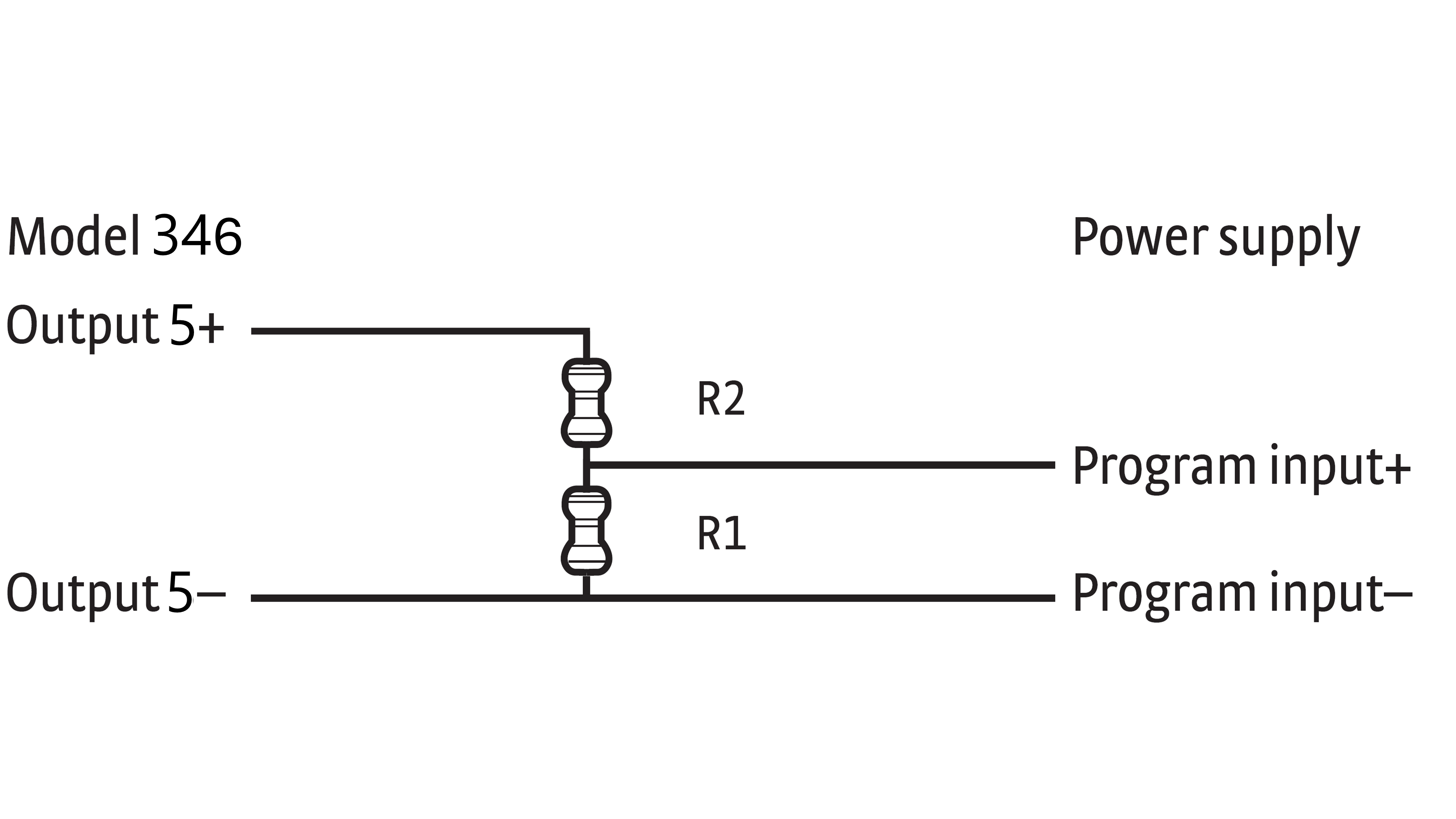
Figure 2.15 Voltage divider circuit for output 5