2.3. Rear Panel Overview and Line Input
This section provides a description of the Model 346 rear panel connections.
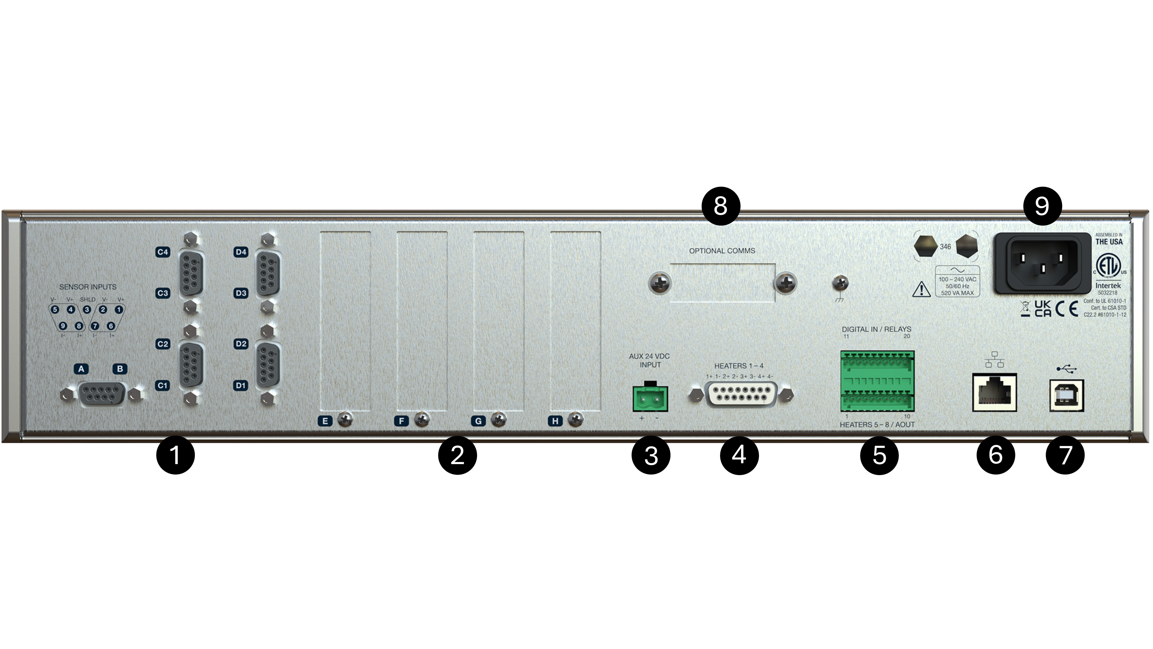
Figure 2.3 Model 346 rear panel
Sensor input connectors Connect up to 10 diode, NTC RTD, or PTC RTD sensors to inputs A, B, C and D.
User option card slots Install up to 4 option cards, including the Model 3401 4-channel scanner and Model 3402 2-channel thermocouple.
Auxiliary 24 VDC input Auxiliary power for future user option cards, presently not used.
Heater outputs Heater outputs 1 to 4, up to 100 W each, for 400 W total.
Terminal block Includes low power voltage source/analog outputs 5 to 8, relays 1 and 2, digital inputs 1 and 2, auxiliary 5 V output low power supply.
RJ-45 Ethernet connector For remote communication over a network.
USB-B connector For remote communication using a virtual COM port.
Optional communication slot For remote communication over GPIB.
Line input assembly Electrical power is provided through the line input assembly.
 Always turn off the instrument before making any rear panel connections. This is especially critical when making sensor to instrument connections.
 Éteignez toujours l’instrument avant d’effectuer toute connexion sur le panneau arrière. Ceci est particulièrement critique lors de la
réalisation de connexions entre le capteur et l’instrument.
Éteignez toujours l’instrument avant d’effectuer toute connexion sur le panneau arrière. Ceci est particulièrement critique lors de la
réalisation de connexions entre le capteur et l’instrument.
Line Input Assembly
This section describes how to properly connect the Model 346 to line power. Please follow these instructions carefully to ensure proper operation of the instrument and the safety of operators.
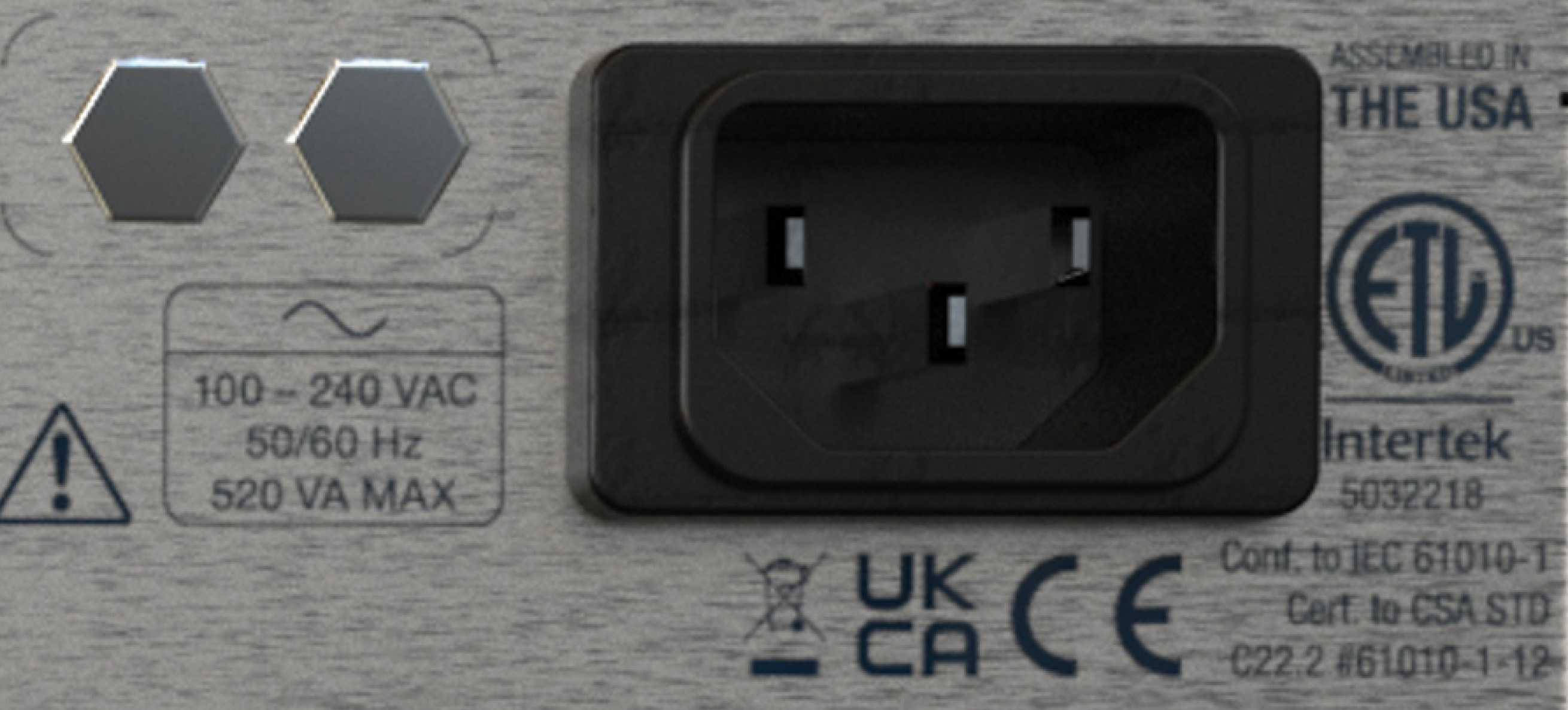
Figure 2.4 Model 346 line input assembly
Line Voltage
The Model 346 operates between the range of 100 VAC to 240 VAC, with 50 Hz or 60 Hz configurations so that it can be operated from line power anywhere in the world. No user configuration is required for different voltage operations
Power Cord
The Model 346 includes a 3-conductor power cord that mates with the IEC 320-C14 line cord receptacle. Line voltage is present on the two outside conductors and the center conductor is a safety ground. The safety ground attaches to the instrument chassis and protects the user in case of a component failure. A CE-approved power cord is included with instruments shipped to Europe; a domestic power cord is included with all other instruments (unless otherwise specified when ordered).
 Always plug the power cord into a properly grounded receptacle to ensure safe instrument
operation. In addition, the receptacle must be protected by a 15/20 A circuit
breaker. The breaker must meet Underwriters Laboratories (UL) and International
Electrotechnical Commission (IEC) safety standards.
Always plug the power cord into a properly grounded receptacle to ensure safe instrument
operation. In addition, the receptacle must be protected by a 15/20 A circuit
breaker. The breaker must meet Underwriters Laboratories (UL) and International
Electrotechnical Commission (IEC) safety standards.
 Branchez toujours le cordon d’alimentation dans une prise correctement mise à la terre
pour assurer un fonctionnement sécuritaire de l’instrument. De plus, la prise doit être
protégée par un disjoncteur de 15/20 A. Le disjoncteur doit être conforme aux Underwriters
Laboratories (UL) et International Normes de sécurité de la Commission électrotechnique
(IEC).
Branchez toujours le cordon d’alimentation dans une prise correctement mise à la terre
pour assurer un fonctionnement sécuritaire de l’instrument. De plus, la prise doit être
protégée par un disjoncteur de 15/20 A. Le disjoncteur doit être conforme aux Underwriters
Laboratories (UL) et International Normes de sécurité de la Commission électrotechnique
(IEC).
Position the Model 346 in such a way to enable easy access to the disconnecting device.
Failure to comply could result in death or injury to personnel.
Positionnez le modèle 346 de manière à permettre un accès facile au dispositif de déconnexion.
Le non-respect de ces consignes peut entraîner la mort ou des blessures au personnel.
Note
If the power supply cord is damaged or lost, it must be replaced. Contact Lake Shore for a replacement to ensure proper voltage, current and type of cord. The power supply cord must not exceed 3 m (10 ft) in length.
The delicate nature of the measurements being taken with this instrument may necessitate additional grounding including ground strapping of the instrument chassis. In these cases the operator’s safety should remain the highest priority and low impedance from the instrument chassis to safety ground should always be maintained.
Power Switch
The power switch is located on the front panel of the Model 346 and turns line power to the instrument on and off. When the button is depressed, power is on. When the line is released, power is off.