2.4. Diode/Resistor Sensor Inputs
This section details how to connect diode and resistor sensors to the Model 346 standard inputs and the 4-channel scanner option card input channels.
Sensor Input Connector and Pinout
The input A to D connectors are standard DE-9 sockets. The sensor connector pins are defined in the figure and table below. Five mating connectors (DE-9 plugs) are included in the connector kit shipped with the instrument. The connectors included with the instrument were selected for their superior shielding capabilities. If additional connectors are required, purchase them from Lake Shore or search locally for full metal connectors that allow connection to the cable shield. Assembly instructions for the provided connectors are available in the D-sub connector guide.
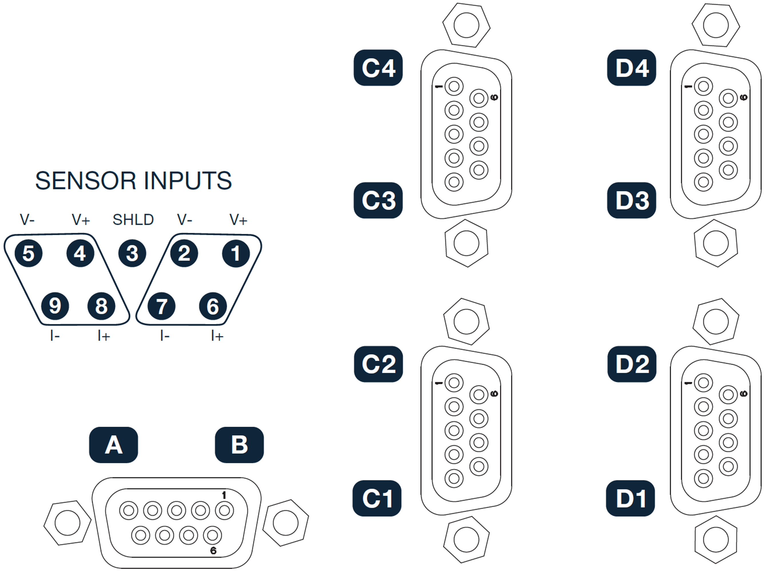
Figure 2.5 Sensor input connectors
Pin |
Symbol |
112-409 Cable |
Description |
|---|---|---|---|
8 |
Sensor 1: I+ |
Brown |
+current source |
9 |
Sensor 1: I- |
White (brown pair) |
-current source |
4 |
Sensor 1: V+ |
Black |
+voltage measure |
5 |
Sensor 1: V- |
White (black pair) |
-voltage measure |
6 |
Sensor 2: I+ |
Orange |
+current source |
7 |
Sensor 2: I- |
White (orange pair) |
-current source |
1 |
Sensor 2: V+ |
Red |
+voltage measure |
2 |
Sensor 2: V- |
White (red pair) |
-voltage measure |
3 |
Shield |
Drain Wire |
sensor measurement common (isolated from chassis) |
Note
In the above table, pins 8, 9, 4, and 5 represent inputs A, C1, C3, D1, and D3, while pins 6, 7, 1, and 2 represent inputs B, C2, C4, D2, and D4.
Sensor Lead Cable
The sensor lead cable used outside the cooling system can be much different from what is used inside. Between the instrument and vacuum shroud, heat leak is not a concern. In this case, choose cabling to minimize error and noise pick up. Larger conductor, 22 AWG to 28 AWG stranded copper wire is recommended because it has low resistance yet remains flexible when several wires are bundled in a cable. The arrangement of wires in a cable is also important. For best results, twist voltage leads V+ and V- together, and twist current leads I+ and I- together. Cover the twisted pairs of voltage and current leads with a braided or foil shield that is connected to the shield pin of the instrument. Pre-made cables from Lake Shore are designed to achieve these requirements (part numbers 112-409-03, 112-409-06, and 112-409-10). Wire color information for these cables is included in Table 2.1.
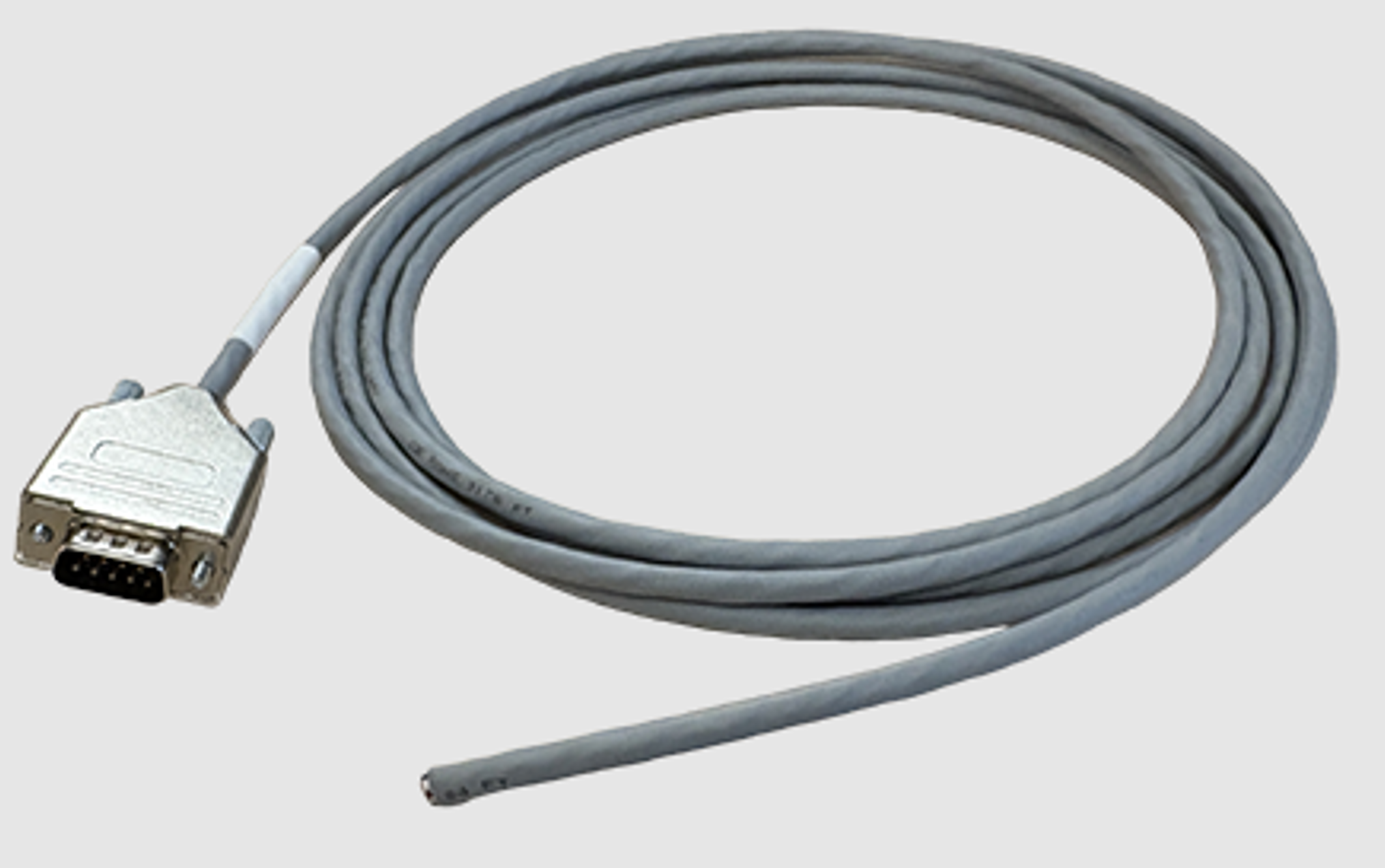
Figure 2.6 Pre-made cable assembly example (112-409-03 sensor cable, 3m)
Instrument specifications are given assuming 3 m (10 ft) of sensor cable. Longer cables, 30 m (100 ft) or more, can be used, but environmental conditions may degrade accuracy and noise specifications.
Grounding and Shielding Sensor Leads
The sensor inputs are isolated from earth ground to reduce the amount of earth ground referenced noise that is present on the measurement leads. Connecting any of the sensor leads to earth ground via the chassis of the instrument, or in the cooling system, will defeat that isolation.
Shielding the sensor lead cable is important to keep external interference/noise from entering the measurement. A shield is a conductive layer that surrounds one or more wires, forming a continuous enclosure to reduce electromagnetic coupling and interference. Foil-only shielding loses effectiveness above 1 MHz, so braid-over foil is better for RF performance.
Note
Sensor leads should never connect to the enclosure or cable shield at any point. Use the shield only for shielding, not as a signal return path.
Types of interference
Interference can range from lower frequencies, such as 50/60 Hz power line cycles, to high frequencies, such as radio frequency (RF) signals from a nearby transmitter.
Low-frequency refers to ranges where wavelengths are very long, and reactive components (inductance and capacitance) have minimal influence. In EMC contexts, this generally means frequencies below a few hundred kilohertz (kHz). High frequency describes ranges where reactive effects dominate, and even short wires exhibit significant inductance. In EMC applications, this typically applies to signals above about one megahertz (MHz).
To mitigate low-frequency AC interference, such as 50/60 Hz from building power, a simple wire connecting the cable shield to earth ground (also known as a pigtail connection), usually mitigates this type of interference, by keeping the shield at zero potential, relative to earth ground. At these low frequencies, the impedance of a pigtail connection is much lower than the capacitive coupling path, making it an effective shielding method.
Above a few MHz, the discussion turns to high-frequency AC interference. At these frequencies, a single-wire “pigtail” connection behaves like an inductor, introducing impedance and degrading shielding performance. Proper RF shielding requires a solid RF connection—a continuous, low-impedance bond, such as a full 360° connection of the cable shield to the sensor input connector metal backshell. This maintains shielding integrity and extends the Faraday cage.
Best Practices
A break in the shield compromises its effectiveness. The best practice is to connect the shield at both ends of the cable to chassis/earth ground (full 360° termination). However, connecting both ends can create ground loops if the instrument chassis, and cryostat chassis, are at different potentials. The common advice to connect the shield at only one end reduces ground loop risk but breaks the Faraday cage, which hurts RF performance (although it still helps with low-frequency interference).
Ensure the instrument chassis shares the same earth ground circuit as the cryostat. If that is not possible, use one or more low-impedance (solid RF) shield connections to minimize potential differences between the two. In extreme circumstances, a Parallel Earth Conductor (PEC) may be required to maintain equipotential bonding and safely carry any ground currents that may occur. A PEC is typically a heavy-gauge conductor or bonded metalwork routed alongside the signal cable and connected at both ends to the chassis earth points of the instrument and cryostat. This approach reduces common-mode impedance and provides a controlled return path for fault currents.
As stated earlier, the sensor input circuit is isolated from chassis/earth ground. Therefore, a connection is still required in the system to connect measurement common to chassis/earth ground. On the measurement input connector, a shield pin (at measurement common) is provided to allow for this connection to occur. Connecting the shield pin (at measurement common) to chassis ground helps stabilize the reference potential and reduce common-mode noise. If measurement common is left floating, it can develop a voltage difference relative to the shield and chassis, causing unwanted currents through cable shields and increasing susceptibility to hum and low-frequency interference. A direct bond between measurement common and chassis provides a predictable return path for these low-frequency currents, improving signal integrity and reducing noise coupling.
Note
Be sure to only make the measurement common and chassis/earth connection in one location. It is recommended to do this using the shield pin located inside the sensor input connector of the Model 346. Making an additional measurement common to chassis/earth connection at the cryostat will likely cause ground loops to form.
Note
The backshells of the input connectors of Model 346 are at chassis/earth ground. Older Lake Shore controllers are not configured this way, and have backshells at isolated measurement common.
The following figure illustrates the recommended techniques mentioned above.
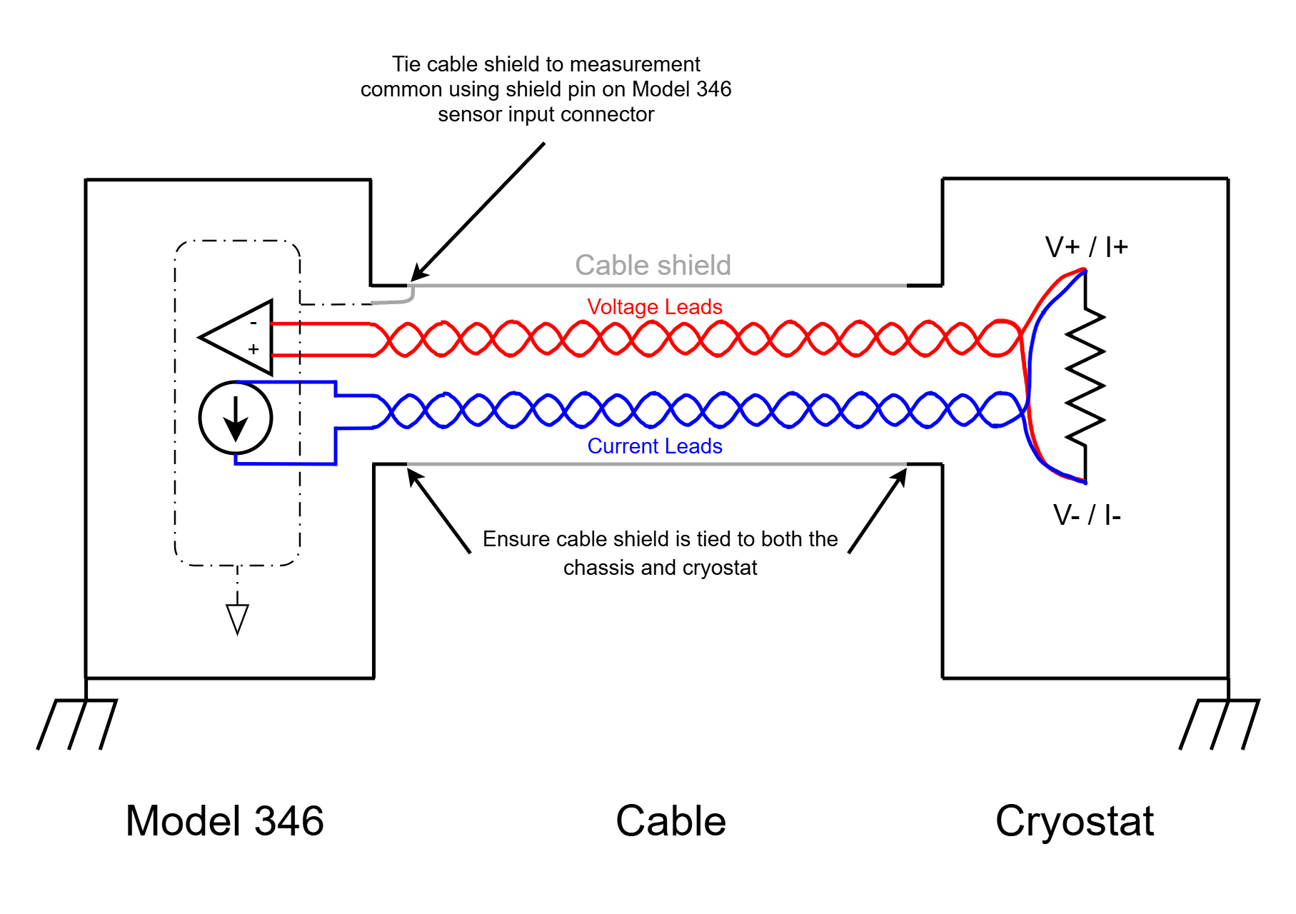
Figure 2.7 Example of sensor wiring and shielding
Sensor Polarity
This section describes the diode/resistor sensor inputs.
Lake Shore sensors are shipped with instructions that indicate which sensor leads are which. It is important to follow these instructions for plus and minus leads (polarity) as well as voltage and current when applicable. Diode sensors do not operate in the wrong polarity; they appear as an open circuit to the instrument. Two-lead resistors can operate with any lead arrangement and the sensor instructions may not specify. Four-lead resistors can be more dependent on lead arrangement.
Note
Follow any specified lead assignment for four-lead resistors. Mixing leads can give a reading that appears correct, but is not accurate.
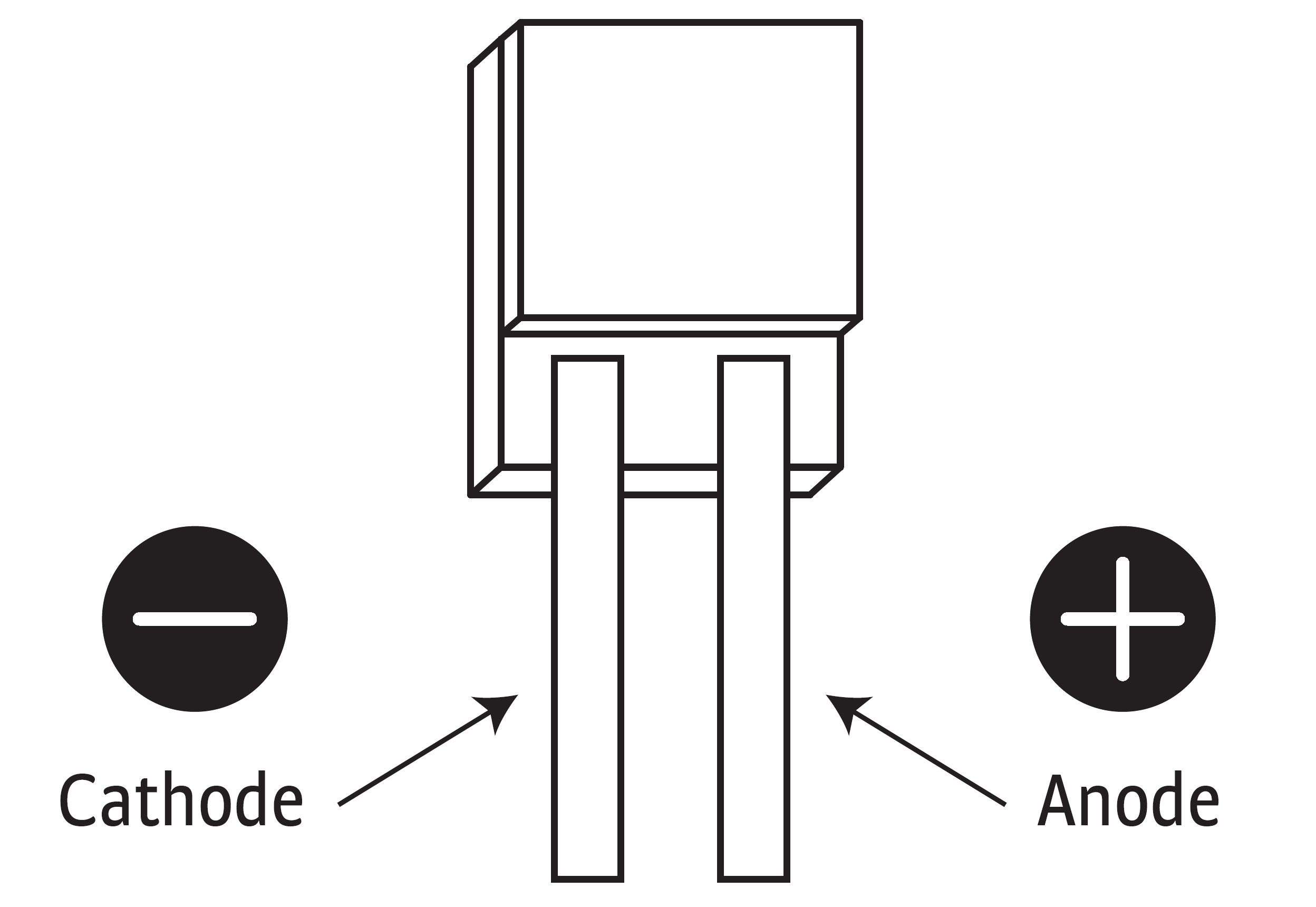
Figure 2.8 DT-670-SD diode sensor leads
Four-Lead Sensor Measurement
All sensors, including both two-lead and four-lead, can be measured with a four-lead technique. The purpose of a four-lead measurement is to eliminate the effect of lead resistance on the measurement. If it is not removed, lead resistance is a direct error when measuring a sensor.
In a four-lead measurement, current leads and voltage leads are run separately up to the sensor. With separate leads there is little current in the voltage leads, so their resistance does not enter into the measurement. Resistance in the current leads will not change the measurement as long as the voltage compliance of the current source is not reached. When two-lead sensors are used in four-lead measurements, the short leads on the sensor have an insignificant resistance.
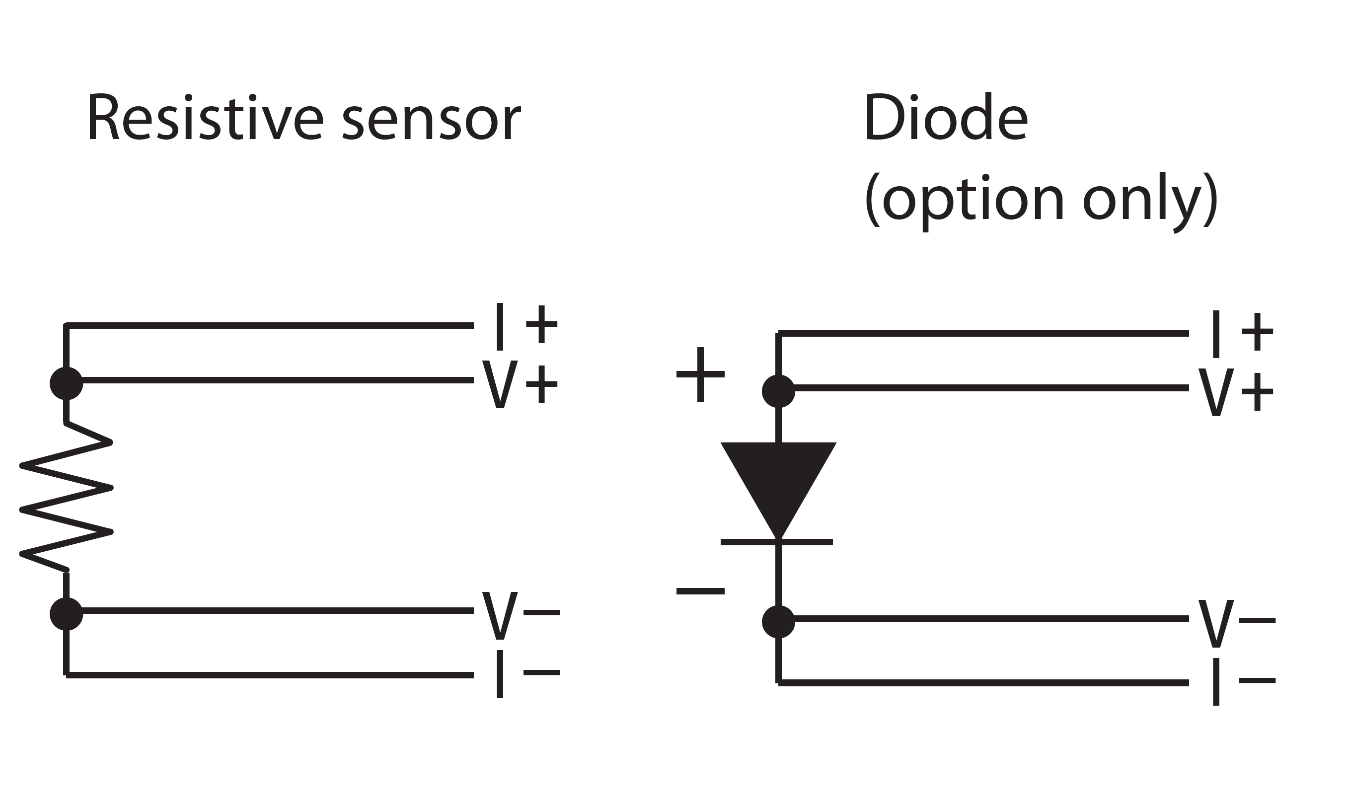
Figure 2.9 4-lead measurement
Two-Lead Sensor Measurement
There are times when crowding in a cryogenic system forces users to read sensors in a two-lead configuration because there are not enough feedthroughs or room for lead wires. If this is the case, attach leads from plus voltage to plus current and minus voltage to minus current at the back of the instrument, or at the vacuum feedthrough
The error in a resistive measurement is the resistance of the lead wire run with current and voltage together. If the leads contribute 2 Ω or 3 Ω to a 10 kΩ reading, the error can probably be tolerated. When measuring voltage for diode sensors, you can calculate the error in voltage as the lead resistance times the current, typically 10 μA.
For example: a 10 Ω lead resistance times 10 μA results in a 0.1 mV error in voltage. Given the sensitivity of a silicon diode at 4.2 K, the error in temperature would be only 3 mK. At 77 K the sensitivity of a silicon diode is lower so the error would be close to 50 mK. This may not be a problem for every user. Connectors are also a big source of error when making two-lead measurements. Connector contact resistance is unpredictable and changes with time and temperature, which may cause a source of error when making two-lead measurements. Refer to Figure 2.10 for an image of a two-lead sensor measurement.
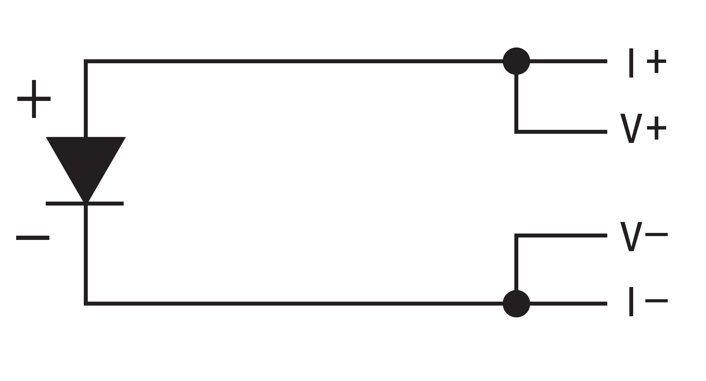
Figure 2.10 2-lead sensor measurement
Lowering Measurement Noise
Proper instrument hardware setup technique is one of the least expensive ways to reduce measurement noise. The suggestions fall into two categories: (1) do not let noise from the outside enter into the measurement, and (2) let the instrument isolation and other hardware features work to their best advantage. Here are some further suggestions:
Use four-lead measurement whenever possible
Do not connect sensor leads to chassis or earth ground
Use twisted shielded cable outside the cooling system
Attach the shield pin, located on the sensor connector, to the cable shield
All cable shields should be connected to earth ground on the instrument chassis
Do not attach more than one cable shield at the other end of the cable
Run different inputs and outputs in their own shielded cable
Use twisted wire inside the cooling system
Use similar technique for heater leads
Use a grounded receptacle for the instrument power cord
Consider ground strapping the instrument chassis to other instruments or computers