7.4. Rear Panel Connectors
The connectors on the rear panel of the Model 346 are defined below.
Diode / Resistor Sensor Inputs (includes 3401 option card)
Sensor Inputs A through D are DE-9 style connectors. There are two sensor inputs per connector. The diagram on the left (labeled SENSOR INPUTS) shows the general sensor pin grouping per DE-9 connector. Pins 8,9,4,5 belong to one input, and pins 6,7,1,2 belong to the other input. You can use either the C1 to C4 or D1 to D4 pin outs to determine 3401 sensor wiring.
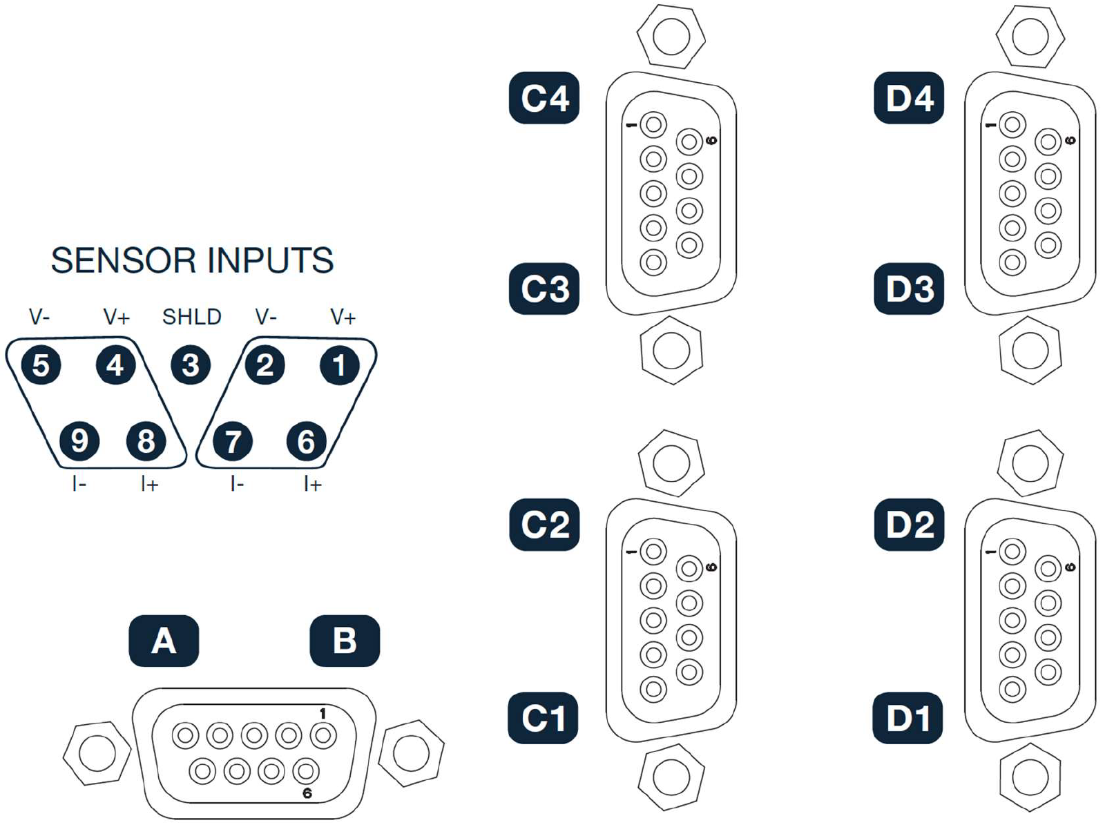
Figure 7.2 Diode / Resistor Sensor Inputs
Pin |
Inputs |
Symbol |
Description |
|---|---|---|---|
8 |
A, C1, C3, D1, D3 |
I+ |
+ current out |
9 |
I- |
- current out |
|
4 |
V+ |
+ voltage in |
|
5 |
V- |
- voltage in |
|
6 |
B, C2, C4, D2, D4 |
I+ |
+ current out |
7 |
I- |
- current out |
|
1 |
V+ |
+ voltage in |
|
2 |
V- |
- voltage in |
|
3 |
n/a |
shield |
Sensor measurement common (isolated from chassis) |
Heater Output
A 15-pin DA-15 style connector is used for the heater outputs. Each heater return is at the same potential as chassis/earth ground. The compliance voltage of each heater output is 50 V minimum, but can reach as high as approximately 53 V, if the heater resistance is higher than the nominal setting. The maximum current that can be sourced from each heater output is approximately 2 A.
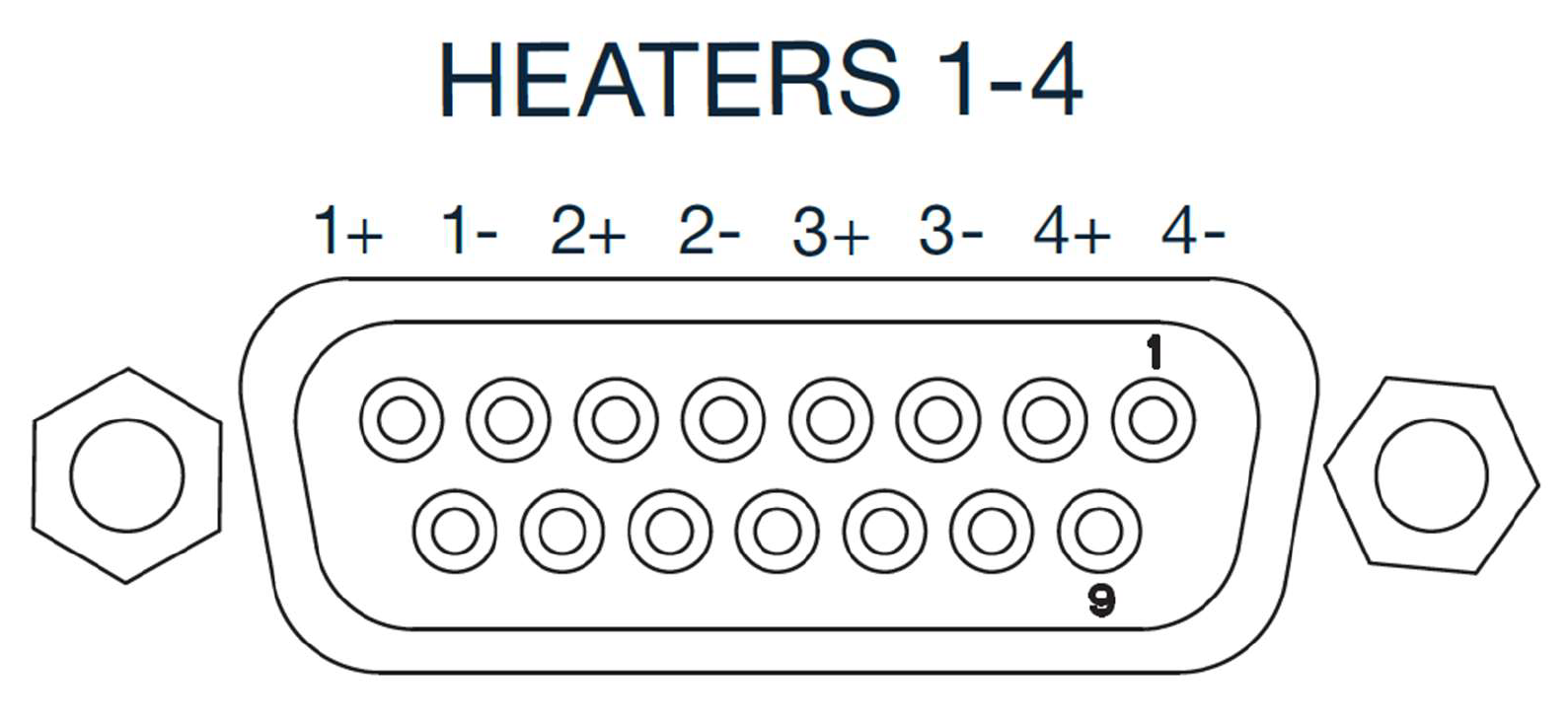
Figure 7.3 Heater Output
Pin |
Description |
|---|---|
8 |
Heater 1 HI |
7 |
Heater 1 LO |
6 |
Heater 2 HI |
5 |
Heater 2 LO |
4 |
Heater 3 HI |
3 |
Heater 3 LO |
2 |
Heater 4 HI |
1 |
Heater 4 LO |
10, 12, 14 |
Additional chassis/earth ground connections |
9, 11, 13, 15 |
No connect |
Digital In / relays / Analog out
A 2 level, 20 pin, 2.5mm terminal block allows access to the following:
Name |
Description |
|---|---|
Analog Out / 1W heaters |
Identifiable as ‘outputs 5-8’, these outputs are 0 to +10V voltage sources, capable of sourcing up to 100mA, at 10V, into a 100Ohm load. |
Relays |
Two relays, each with a normally open, normally closed, and common terminal. Contact rating of 30VDC at 2A. |
Digital Input |
Optically isolated inputs that have a safe input voltage range of -5V to +35V, with a max low level input voltage of 1V and a minimum high level input voltage of 4V |
5V supply |
Isolated +5V supply (100mA max). As an example, it can be used with a relay to drive high impedance digital inputs used for process control in a system. |
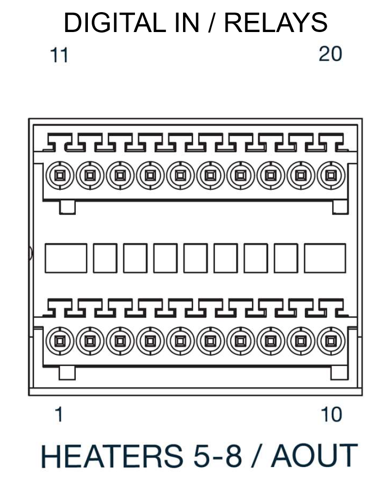
Figure 7.4 Digital In / relays / Analog out
Pin |
Description |
|---|---|
1 |
Analog Out 1 + |
2 |
Analog Out 1 - |
3 |
Analog Out 2 + |
4 |
Analog Out 2 - |
5 |
Analog Out 3 + |
6 |
Analog Out 3 - |
7 |
Analog Out 4 + |
8 |
Analog Out 4 - |
9 |
+5V isolated supply |
10 |
+5V isolated supply return |
11 |
Relay 1 normally closed |
12 |
Relay 1 common |
13 |
Relay 1 normally open |
14 |
Relay 2 normally closed |
15 |
Relay 2 common |
16 |
Relay 2 normally open |
17 |
Digital Input 1 + |
18 |
Digital Input 1 - |
19 |
Digital Input 2 + |
20 |
Digital Input 2 - |
24VDC Auxiliary Power
A 0.2 in (5.08 mm) 2-pin terminal block allows user-provided 24 VDC to be supplied to the Model 346 to provide auxiliary power to possible future option cards that may require it. The return of this external 24 VDC is connected to the Model 346 chassis ground.
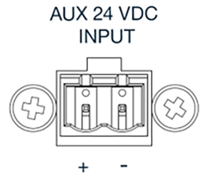
Figure 7.5 AUX 24 VDC Input
USB B Connector
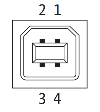
Figure 7.6 USB pin and connector
Pin |
Name |
Description |
|---|---|---|
1 |
VCC |
+5 VDC |
2 |
D- |
Data – |
3 |
D+ |
Data + |
4 |
GND |
Ground |
Ethernet Connector
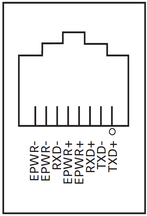
Figure 7.7 Ethernet pin and connector
Pin |
Symbol |
Description |
|---|---|---|
1 |
TXD+ |
Transmit data+ |
2 |
TXD- |
Transmit data- |
3 |
RXD+ |
Receive data+ |
4 |
EPWR+ |
Power from switch+ (not used) |
5 |
EPWR+ |
Power from switch+ (not used) |
6 |
RXD- |
Receive data- |
7 |
EPWR- |
Power from switch- (not used) |
8 |
EPWR- |
Power from switch- (not used) |
IEEE-488 Interface Connector (optional)
Use the cables specified in the IEEE-488 standard. The cable has 24 conductors with an outer shield. The connectors are 24-way Amphenol 57 Series (or equivalent) with piggyback receptacles to allow daisy chaining in multiple device systems.
The total length of cable allowed in a system is 2 m for each device on the bus, or 20 m maximum. The Model 346 can drive a bus of up to 10 devices. The figure below shows the IEEE-488 interface connector pin location and signal names as viewed from the Model 346 rear panel.
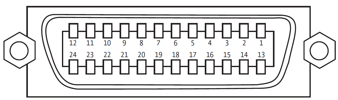
Figure 7.8 IEEE-488 interface
Pin |
Symbol |
Description |
|---|---|---|
1 |
DIO 1 |
Data input/output line 1 |
2 |
DIO 2 |
Data input/output line 2 |
3 |
DIO 3 |
Data input/output line 3 |
4 |
DIO 4 |
Data input/output line 4 |
5 |
EOI |
End or identify |
6 |
DAV |
Data valid |
7 |
NRFD |
Not ready for data |
8 |
NDAC |
No data accepted |
9 |
IFC |
Interface clear |
10 |
SRQ |
Service request |
11 |
ATN |
Attention |
12 |
SHIELD |
Cable shield |
13 |
DIO 5 |
Data input/output line 5 |
14 |
DIO 6 |
Data input/output line 6 |
15 |
DIO 7 |
Data input/output line 7 |
16 |
DIO 8 |
Data input/output line 8 |
17 |
REN |
Remote enable |
18 |
GND 6 |
Ground wire—twisted pair with DAV |
19 |
GND 7 |
Ground wire—twisted pair with NRFD |
20 |
GND 8 |
Ground wire—twisted pair with NDAC |
21 |
GND 9 |
Ground wire—twisted pair with IFC |
22 |
GND 10 |
Ground wire—twisted pair with SRQ |
23 |
GND 11 |
Ground wire—twisted pair with ATN |
24 |
GND |
Logic ground |