6.6. Status and Error Reporting
Status System Overview
The MeasureReady™ M81-SSM implements a status system compliant to the SCPI-99 standard. The SCPI status system is derived from the status system called out in Chapter 11 of the IEEE 488.2 standard. The status system provides a method of recording and reporting instrument information. At the center of the status system is the status byte register. This register contains summary bits from other status registers, providing the user one register to periodically query to determine if further interrogation of the instrument is required.
In addition to the status byte and its complementary service request enable register, the status system is made up of standard, questionable, and operation status register sets. Each one of those register sets comprises three types of registers: condition, event, and enable. In addition, the status system contains an output buffer and error queue. A diagram of the status system is shown below.
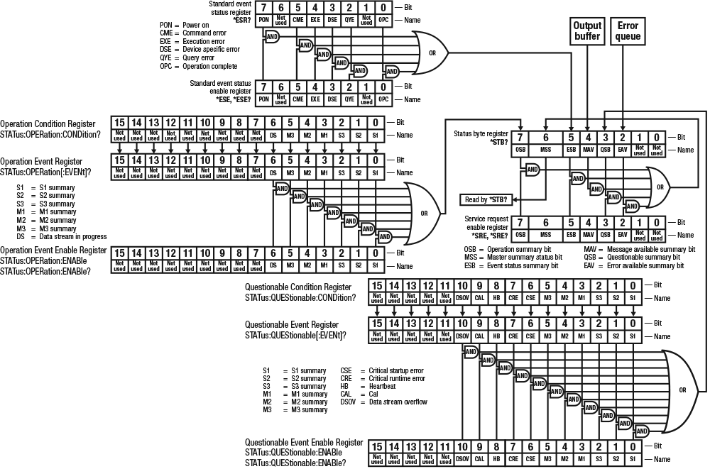
Figure 6.5 M81-SSM status system
Status Byte Register
The status byte register, typically referred to as the status byte, is a non-latching, read-only register that contains all of the summary bits from the register sets. The status of the summary bits are controlled from the register sets as explained in section 4.3.2.1 to section 4.3.2.5. The status byte also contains the Master Summary Status (MSS) bit. This bit is used to report if any of the summary bits are set via the *STB? command. The status of the MSS bit is controlled by the summary bits and the service request enable register.
Service Request Enable Register
The service request enable register determines which summary bits in the status byte will set the MSS bit of the status byte. The user may write to or read from the service request enable register. Each status byte summary bit is logically ANDed to the corresponding enable bit of the service request enable register. When a service request enable register bit is set by the user, and the corresponding summary bit is set in the status byte, the MSS bit of the status byte will be set.
Conditional Registers
Each register set (except the standard event register set) includes a condition register. The condition register constantly monitors the instrument status. The data bits are real-time and are not latched or buffered. The register is read-only.
Event Registers
Each register set includes an event register. Bits in the event register correspond to various system events and latch when the event occurs. Once an event bit is set, subsequent events corresponding to that bit are ignored. Set bits remain latched until the register is cleared by a query command (such as *ESR?) or a *CLS command. The register is read-only.
Enable Registers
Each register set includes an enable register. An enable register determines which bits in the corresponding event register will set the summary bit for the register set in the status byte. The user may write to or read from an enable register. Each event register bit is logically ANDed to the corresponding enable bit of the enable register. When an enable register bit is set by the user, and the corresponding bit is set in the event register, the output (summary) of the register will be set, which in turn sets the master summary status bit of the status byte register.
Reading Registers
Any register in the status system may be read using the appropriate query command. The response to a query will be a decimal value that corresponds to the binary-weighted sum of all bits in the register.
Bit |
Decimal |
Weighting |
|---|---|---|
0 |
1 |
\(2^0\) |
1 |
2 |
\(2^1\) |
2 |
4 |
\(2^2\) |
3 |
8 |
\(2^3\) |
4 |
16 |
\(2^4\) |
5 |
32 |
\(2^5\) |
6 |
64 |
\(2^6\) |
7 |
128 |
\(2^7\) |
Programming Registers
The only registers that may be programmed by the user are the enable registers. All other registers in the status system are read-only registers. To program an enable register, send a decimal value that corresponds to the desired binary-weighted sum of all bits in the register
Status Byte Register
The summary messages from the event registers and the output buffer set or clear the summary bits of the status byte register. These summary bits are not latched. Clearing an event register will clear the corresponding summary bit in the status byte register. Reading all messages in the output buffer, including any pending queries, will clear the message available bit. Reading all errors out of the queue will clear the error available bit. The bits of the status byte register are described as follows:
Operation Summary (OSB), Bit 7: This bit is set when an enabled operation event has occurred
Master Summary Status (MSS), Bit 6: This bit is set when a summary bit and the summary bit’s corresponding enable bit in the service request enable register are set. A *STB? will read the status of the MSS bit (along with all of the summary bits), but also will not clear it. To clear the MSS bit, either clear the event register that set the summary bit or disable the summary bit in the service request Enable register.
Event Summary (ESB), Bit 5: This bit is set when an enabled standard event has occurred
Message Available (MAV), Bit 4: This bit is set when a message is available in the output buffer
Questionable Summary (QSB), Bit 3: This bit is set when an enabled questionable event has occurred
Error Available (EAV), Bit 2: This bit is set when an error is available in the error queue
Service Request Enable Register
The service request enable register is programmed by the user and determines which summary bits of the status byte may set bit 6 (MSS). Enable bits are logically ANDed with the corresponding summary bits. Whenever a summary bit is set by an event register and its corresponding enable bit is set by the user, bit 6 will be set. The Service Request Enable command (*SRE) programs the Service Request Enable Register and the query command (*SRE?) reads it.
Standard Event Status Register Set
The standard event status register reports the following interface-elated instrument events: power on detected, command syntax errors, command execution errors, query errors, and operation complete. Any or all of these events may be reported in the standard event summary bit through the enable register. The standard event status enable command (*ESE) programs the enable register and the query command (*ESE?) reads it. *ESR? reads and clears the standard event status register.
Power On (PON), Bit 7: This bit is set to indicate an instrument off-on transition
Command Error (CME), Bit 5: This bit is set if a command error has been detected since the last reading. This means that the instrument could not interpret the command due to a syntax error, an unrecognized header, unrecognized terminators, or an unsupported command
Execution Error (EXE), Bit 4: This bit is set if an execution error has been detected. This occurs when the instrument is instructed to do something not within its capabilities. A typical example of this are command parameters that are outside the instrument’s acceptable bounds.
Device Specific Error (DSE), Bit 3: This bit is set if an error occurs that does not fall into another category defined as a standard event. Examples include if the M81-SSM is unable to set its date/time or time zone.
Query Error (QYE), Bit 2: This bit indicates a query error. It occurs rarely and involves loss of data because the output queue is full.
Operation Complete (OPC), Bit 0: When *OPC is sent, this bit will be set when the instrument has completed all pending operations. The operation of this bit is not related to the *OPC? command, which is a separate interface feature.
Operation Register Set
The operation event register reports the instrument events that are considered part of normal operation. Any or all of these events may be reported in the operation event summary bit through the enable register. The operation event enable command (STATus:OPERation:ENABle) programs the enable register and the query command (STATus:OPERation:ENABle?) reads it. STATus:OPERation[:EVENt]? reads and clears the operation event register. STATus:OPERation:CONDition? reads the operation condition register.
S1-3 Summary, Bit 0-2: This bit is a summary of the operation register for a particular source module
M1-3 Summary, Bit 3-5: This bit is a summary of the operation register for a particular mesure module
Data Stream in Progress (DS), Bit 6: This bit is set when a datastream is in progress.
The source modules have their own operational register sets and are accessed from the STATus:OPERation:SOURce# subsystem with the following bit definition:
V Limit (VLIM), Bit 0: This bit is set when the module voltage limit is activated.
I Limit (ILIM), Bit 1: This bit is set when the module current limit is activated.
Sweeping (SWP), Bit 2: This bit is set when the module is sweeping a parameter.
The measure modules have their own operational register sets and are accessed from the STATus:OPERation:SENSe# subsystem with the following bit definition:
Overload (OVLD), Bit 0: This bit is set when the measurement is higher than the maximum for the range.
Settling (SETL), Bit 1: This bit is set when the module hardware is settling due to a configuration change.
Unlocked (UNLK), Bit 2: This bit is set if the PLL has not attained lock on the input frequency.
Questionable Register Set
The questionable status register reports various states of the instrument that could indicate the quality of the output signal may be compromised. Any or all of these events may be reported in the questionable event summary bit through the enable register. The questionable event enable command (STATus:QUEStionable:ENABle) programs the enable register and the query command (STATus:QUEStionable:ENABle?) reads it. STATus:QUEStionable[:EVENt]? reads and clears the questionable event register. STATus:QUEStionable:CONDition? reads the questionable condition register.
S1-3 Summary, Bit 0-2: This bit is a summary of the questionable register for a particular measure module
M1-3 Summary, Bit 3-5: This bit is a summary of the questionable register for a particular source module
Critical Startup Error (CSE), Bit 6: This bit is set if a hardware issue was detected during startup
Critical Runtime Error (CRE), Bit 7: This bit is set if a hardware issue was detected during runtime
Internal Communication Failure (HB), Bit 8: This bit is set if internal communications are interrupted
Calibration Error (CAL), Bit 9: This bit is set if corrupted or default calibration data is detected
Data Stream Overflow (DSOV), Bit 10: This bit is set if data was lost during a stream because of buffer overflow
The source and measure modules have their own questionable register sets. These register sets are accessed through the STATus:QUEStionable:SOURce# and STATus:QUEStionable:SENSe# subsystems respectfully. They share the following bit definitions:
Read Error (RE), Bit 0: This bit is set when module communication fails.
Unrecognized Module Error (UME), Bit 1: This bit is set when the connected module was successfully identified, but is not supported by the instrument firmware. The firmware must be updated to support this module.
Port Direction Error (PDE), Bit 2: This bit indicates that the module is plugged into the wrong port type. Source modules must be connected to source ports. Measure modules must be connected to measure ports.
Factory Calibration Failure (FCF), Bit 3: This bit is set if the factory calibration process failed for this module.
Self Calibration Failure (SCF), Bit 4: This bit is set if the last self calibration attempt failed.
Error Messages
As called out in the SCPI-99 specification, the M81-SSM implements an error queue that contains coded error and status messages thrown during operation. SCPI 99 defines error messages with a negative (-) prefix as standard errors, common to all SCPI compliant instruments. Error messages with a positive prefix (+) are allocated to instrument manufacturers for instrument specific messages. Presently, the M81-SSM does not implement any instrument specific messages. All M81-SSM specific errors and status are captured in the status register system.
Coded error and status messages can be retrieved and cleared over the remote interface using the following commands:
SYSTem:ERRor:ALL?
SYSTem:ERRor:CLEar
SYSTem:ERRor:COUNt?
SYSTem:ERRor[:NEXT]?
The queue is implemented with a “First In, First Out” (FIFO) approach. This means, if the M81-SSM adds multiple messages to the queue in a given period of time, issuing the SYSTem:ERRor[:NEXT]? query will return the message that was added to the queue first, and, subsequently remove it from the queue.
SCPI 99 categorizes its standard errors into logical groups that match bit definitions in the standard event status register. When the M81-SSM adds an error message to the queue, a bit in the standard event status register will be set as well. The error code range table shown below lists the error code ranges, title, and the corresponding bit in the standard event status register that gets set when the error or status is added to the queue.
Error code range |
Description |
Standard event register bit |
|---|---|---|
-100 to -184 |
Command errors |
5 |
-200 to -294 |
Execution errors |
4 |
-300 to -365 |
Device specific errors |
3 |
-400 to -440 |
Query errors |
2 |
A comprehensive list of standard SCPI error codes descriptions can be found in chapters 21.8.9 through 21.8.16 of the official SCPI 99 standard, located on the IVI website.
Note
The M81-SSM does not implement every error code listed in the standard.