Status and Error Reporting
Status System Overview
The Model 346 implements a status system compliant with the IEEE-488.2 standard. The status system provides a method of recording and reporting the status of the instrument, readings, and installed option cards. At the center of the status system is the status byte register. This register contains summary bits from other status registers, providing the user one register to periodically query to determine if further interrogation of the instrument is required.
In addition to the status byte and its complementary service request enable register, the status system is made up of standard, questionable, and operation status register sets. Each one of those register sets comprises three types of registers: condition, event, and enable. In addition, the status system contains an output buffer and error queue. A diagram of the status system is shown below.
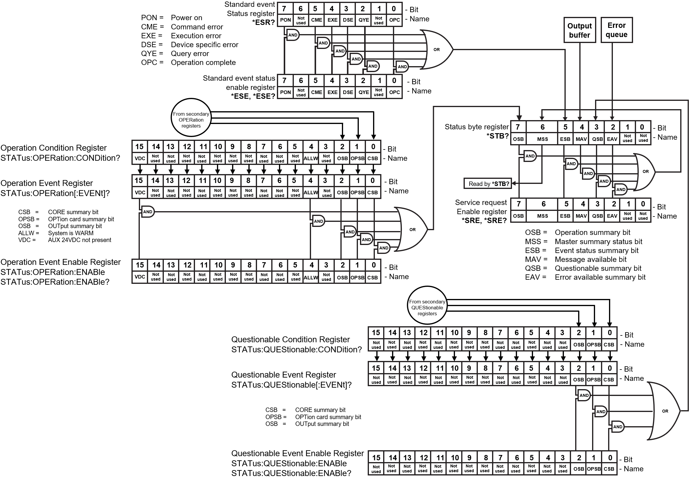
Figure 5.4 Top-level status diagram
Along with the registers shown in the diagram above, both the operation and questionable registers are further divided into a tree of secondary registers:
CORE: the core thermometry inputs available on every Model 346. Each bit represents summary information for inputs A, B, C1 to C4 and D1 to D4.
OPTion: Because an input option can contain no more than 4 channels, this 16-bit register contains summary data for each input option card E, F, G, and H. The meaning of the information depends on the type of input card installed.
OUTput: contains summary data for heater outputs 1 to 4, analog outputs 5 to 8, and heater groups 9 and 10.
Overview of register types
Status Byte Register
The status byte register, typically referred to as the status byte, is a non-latching, read-only register that contains all of the summary bits from the register sets. The status of the summary bits are controlled from the register sets as explained below. The status byte also contains the Master Summary Status (MSS) bit. This bit is used to report if any of the summary bits are set via the *STB? command. The status of the MSS bit is controlled by the summary bits and the service request enable register.
Service Request Enable Register
The service request enable register determines which summary bits in the status byte will set the MSS bit of the status byte. The user may write to or read from the service request enable register. Each status byte summary bit is logically ANDed to the corresponding enable bit of the service request enable register. When a service request enable register bit is set by the user, and the corresponding summary bit is set in the status byte, the MSS bit of the status byte will be set.
Conditional Registers
Each register set (except the standard event register set) includes a condition register. The condition register constantly monitors the instrument status. The data bits are real-time and are not latched or buffered. The register is read-only.
Event Registers
Each register set includes an event register. Bits in the event register correspond to various system events and latch when the event occurs. Once an event bit is set, subsequent events corresponding to that bit are ignored. Set bits remain latched until the register is cleared by a query command (such as *ESR?) or a *CLS command. The register is read-only.
Enable Registers
Each register set includes an enable register. An enable register determines which bits in the corresponding event register will set the summary bit for the register set in the status byte. The user may write to or read from an enable register. Each event register bit is logically ANDed to the corresponding enable bit of the enable register. When an enable register bit is set by the user, and the corresponding bit is set in the event register, the output (summary) of the register will be set, which in turn sets the master summary status bit of the status byte register.
Reading Registers
Any register in the status system may be read using the appropriate query command. The response to a query will be a decimal value that corresponds to the binary-weighted sum of all bits in the register.
Bit |
Decimal |
Weighting |
|---|---|---|
0 |
1 |
\(2^0\) |
1 |
2 |
\(2^1\) |
2 |
4 |
\(2^2\) |
3 |
8 |
\(2^3\) |
4 |
16 |
\(2^4\) |
5 |
32 |
\(2^5\) |
6 |
64 |
\(2^6\) |
7 |
128 |
\(2^7\) |
8 |
256 |
\(2^8\) |
9 |
512 |
\(2^9\) |
10 |
1024 |
\(2^{10}\) |
11 |
2048 |
\(2^{11}\) |
12 |
4096 |
\(2^{12}\) |
13 |
8192 |
\(2^{13}\) |
14 |
16384 |
\(2^{14}\) |
15 |
32768 |
\(2^{15}\) |
Programming Registers
The only registers that may be programmed by the user are the enable registers. All other registers in the status system are read-only registers. To program an enable register, send a decimal value that corresponds to the desired binary-weighted sum of all bits in the register
Standard event register definitions
Status Byte Register
The summary messages from the event registers and the output buffer set or clear the summary bits of the status byte register. These summary bits are not latched. Clearing an event register will clear the corresponding summary bit in the status byte register. Reading all messages in the output buffer, including any pending queries, will clear the message available bit. Reading all errors out of the queue will clear the error available bit. The bits of the status byte register are described as follows:
Operation Summary (OSB), Bit 7: This bit is set when an enabled operation event has occurred
Master Summary Status (MSS), Bit 6: This bit is set when a summary bit and the summary bit’s corresponding enable bit in the service request enable register are set. A *STB? will read the status of the MSS bit (along with all of the summary bits), but also will not clear it. To clear the MSS bit, either clear the event register that set the summary bit or disable the summary bit in the service request Enable register.
Event Summary (ESB), Bit 5: This bit is set when an enabled standard event has occurred
Message Available (MAV), Bit 4: This bit is set when a message is available in the output buffer
Questionable Summary (QSB), Bit 3: This bit is set when an enabled questionable event has occurred
Error Available (EAV), Bit 2: This bit is set when an error is available in the error queue
Service Request Enable Register
The service request enable register is programmed by the user and determines which summary bits of the status byte may set bit 6 (MSS). Enable bits are logically ANDed with the corresponding summary bits. Whenever a summary bit is set by an event register and its corresponding enable bit is set by the user, bit 6 will be set. The Service Request Enable command (*SRE) programs the Service Request Enable Register and the query command (*SRE?) reads it.
Standard Event Status Register Set
The standard event status register reports the following interface-related instrument events: power on detected, command syntax errors, command execution errors, query errors, and operation complete. Any or all of these events may be reported in the standard event summary bit through the enable register. The standard event status enable command (*ESE) programs the enable register and the query command (*ESE?) reads it. *ESR? reads and clears the standard event status register.
Power On (PON), Bit 7: This bit is set to indicate an instrument off-on transition
Command Error (CME), Bit 5: This bit is set if a command error has been detected since the last reading. This means that the instrument could not interpret the command due to a syntax error, an unrecognized header, unrecognized terminators, or an unsupported command
Execution Error (EXE), Bit 4: This bit is set if an execution error has been detected. This occurs when the instrument is instructed to do something not within its capabilities. A typical example of this are command parameters that are outside the instrument’s acceptable bounds.
Device Specific Error (DSE), Bit 3: This bit is set if an error occurs that does not fall into another category defined as a standard event. Examples include if the Model 346 is unable to set its date/time or time zone.
Query Error (QYE), Bit 2: This bit indicates a query error. It occurs rarely and involves loss of data because the output queue is full.
Operation Complete (OPC), Bit 0: When *OPC is sent, this bit will be set when the instrument has completed all pending operations. The operation of this bit is not related to the *OPC? command, which is a separate interface feature.
Operational register definitions
The operation event register set reports the instrument events that are considered part of normal operation. Any or all of these events may be reported in the operation event summary bit through the enable register. The operation event enable command (STATus:OPERation:ENABle) programs the enable register and the query command (STATus:OPERation:ENABle?) reads it. STATus:OPERation[:EVENt]? reads and clears the operation event register. STATus:OPERation:CONDition? reads the operation condition register.
In addition to the primary operation register, there are several secondary registers with their own summary bits, which in turn, feed into the primary operation register. The following diagram illustrates the breakdown of the secondary operational registers.
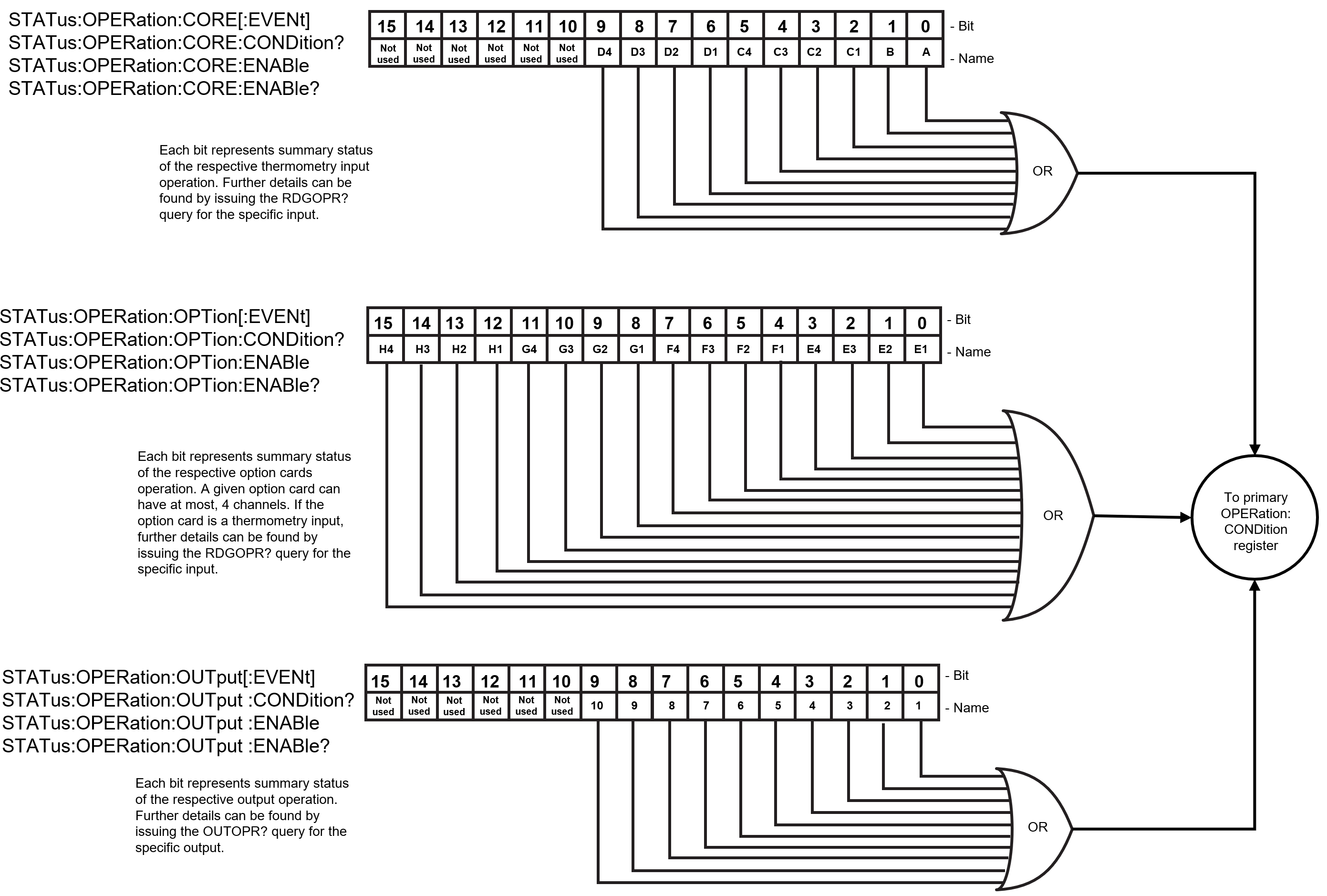
Figure 5.5 Operational register breakdown
STATus:OPERation
This is primary operation status register. Each bit can be logically ORed together to set the operation summary bit (bit 7)in the status byte register (*STB?).
The bits of this register are described as follows:
AUX 24VDC not present (VDC), Bit 15: This bit is set when the auxiliary 24VDC power is not present. This can occur when the power supply is not connected, or if the supply is not providing the required voltage, or the polarity is inverted.
System is WARM (ALLW), Bit 4: This bit is set when using Warm-up mode. When all the outputs report as warm, this bit will be set.
Output card summary (OPSB), Bit 2: This is a summary bit that is set when a bit is set in the STATus:OPERation:OUTput[:EVENt] register and its corresponding :ENABle bit is set.
Option card summary (OPSB), Bit 1: This is a summary bit that is set when a bit is set in the STATus:OPERation:OPTion[:EVENt] register and its corresponding :ENABle bit is set.
CORE Summary (CSB), Bit 0: This is a summary bit that is set when a bit is set in the STATus:OPERation:CORE[:EVENt] register and its corresponding :ENABle bit is set.
STATus:OPERation:CORE
This is a secondary operation status register. Each bit can be logically ORed together to set the core summary bit (bit 0) in the primary STATus:OPERation register.
Each bit is a summary of the operational status of one of the core thermometry inputs available on every Model 346. The inputs are A, B, C1 to C4 and D1 to D4. The mapping of bits to inputs is as follows:
Bit |
Bit weighting |
Input designator |
|---|---|---|
0 |
1 |
A |
1 |
2 |
B |
2 |
4 |
C1 |
3 |
8 |
C2 |
4 |
16 |
C3 |
5 |
32 |
C4 |
6 |
64 |
D1 |
7 |
128 |
D2 |
8 |
256 |
D3 |
9 |
512 |
D4 |
If a bit is set, more operational status information can be found by issuing the RDGOPR? query for the input.
STATus:OPERation:OPTion
This is a secondary operation status register. Each bit can be logically ORed together to set the option summary bit (bit 1) in the primary STATus:OPERation register.
Each bit is a summary of the operational status of the input channels of option cards E, F, G, and H. An option card can have at most, 4 channels. Because an input option can contain no more than 4 channels, this 16-bit register contains summary data for each input option card E, F, G, and H.
The meaning of the information depends on the type of input card installed. Presently, there are only two types of input option cards, the 3401 scanner, and the 3402 thermocouple. Similar to the CORE behavior, if a given channel summary bit is set, further details can be found by issuing the RDGOPR? query for the specific input channel.
The mapping of bits to inputs is as follows:
Bit |
Bit weighting |
Input channel designator |
|---|---|---|
0 |
1 |
Option Card E channel 1 |
1 |
2 |
Option Card E channel 2 |
2 |
4 |
Option Card E channel 3 |
3 |
8 |
Option Card E channel 4 |
4 |
16 |
Option Card F channel 1 |
5 |
32 |
Option Card F channel 2 |
6 |
64 |
Option Card F channel 3 |
7 |
128 |
Option Card F channel 4 |
8 |
256 |
Option Card G channel 1 |
9 |
512 |
Option Card G channel 2 |
10 |
1024 |
Option Card G channel 3 |
11 |
2048 |
Option Card G channel 4 |
12 |
4096 |
Option Card H channel 1 |
13 |
8192 |
Option Card H channel 2 |
14 |
16384 |
Option Card H channel 3 |
15 |
32768 |
Option Card H channel 4 |
STATus:OPERation:OUTput
This is a secondary operation status register. Each bit can be logically ORed together to set the output summary bit (bit 2) in the primary STATus:OPERation register.
Each bit is a summary of the operational status of each output. Outputs are made up of heater outputs 1 to 4, analog outputs 5 to 8, and heater groups 9 and 10.
The mapping of bits to outputs is as follows:
Bit |
Bit Weighting |
Output Designator |
|---|---|---|
0 |
1 |
Output 1 |
1 |
2 |
Output 2 |
2 |
4 |
Output 3 |
3 |
8 |
Output 4 |
4 |
16 |
Output 5 |
5 |
32 |
Output 6 |
6 |
64 |
Output 7 |
7 |
128 |
Output 8 |
8 |
256 |
Output 9 |
9 |
512 |
Output 10 |
If a bit is set, more operational status information can be found by issuing the OUTOPR? query for the output.
Questionable register definitions
The questionable status register reports various states of the instrument that could indicate the quality of the output signal may be compromised. Any or all of these events may be reported in the questionable event summary bit through the enable register. The questionable event enable command (STATus:QUEStionable:ENABle) programs the enable register and the query command (STATus:QUEStionable:ENABle?) reads it. STATus:QUEStionable[:EVENt]? reads and clears the questionable event register. STATus:QUEStionable:CONDition? reads the questionable condition register.
In addition to the primary questionable register, there are several secondary registers with their own summary bits, which in turn, feed into the primary questionable register. The following diagram illustrates the breakdown of the secondary questionable registers.
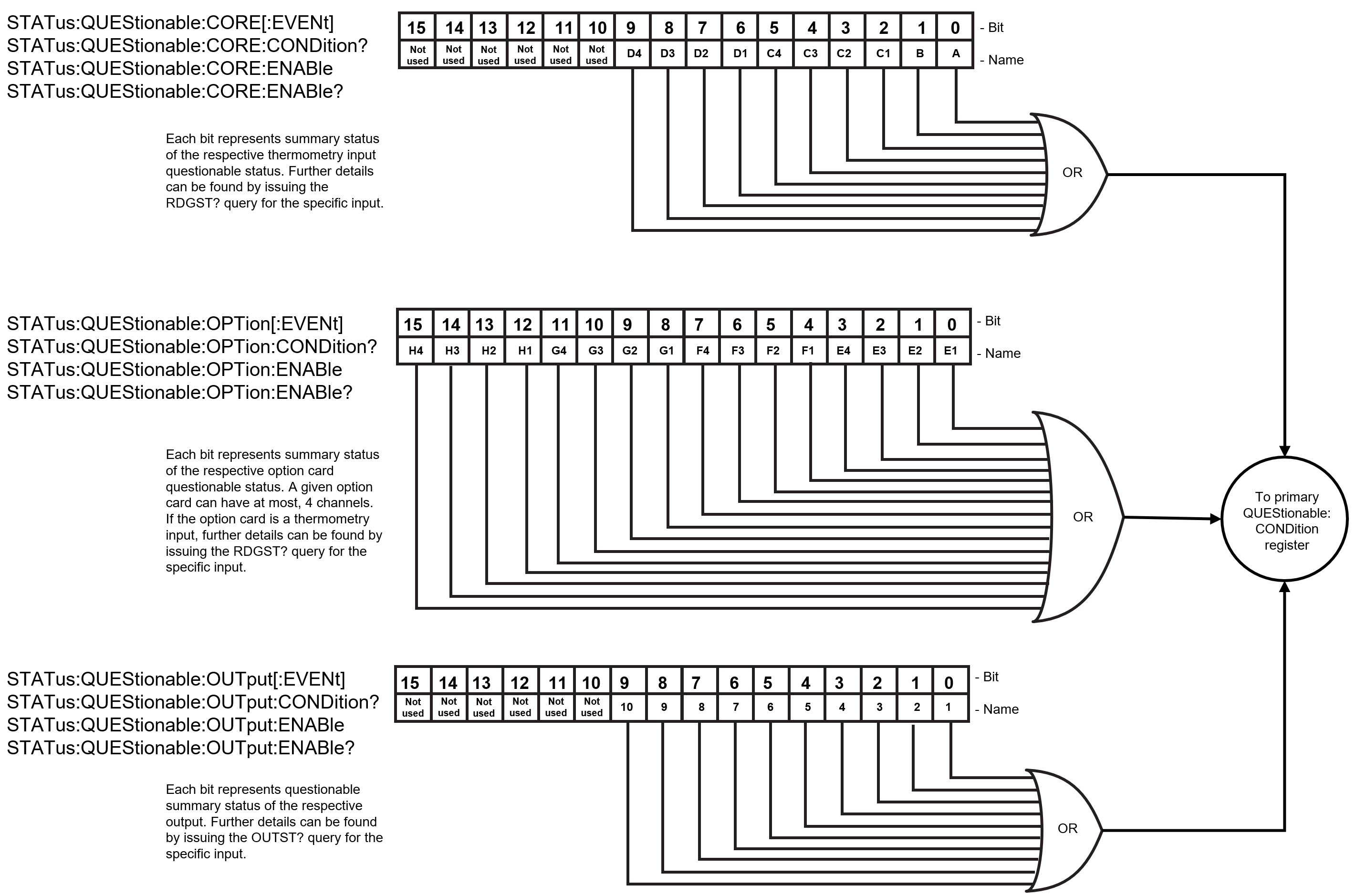
Figure 5.6 Questionable register breakdown
STATus:QUEStionable
This is primary questionable status register. Each bit can be logically ORed together to set the questionable summary bit (bit 3) in the status byte register (*STB?).
The bits of this register are described as follows:
Output card summary (OPSB), Bit 2: This is a summary bit that is set when a bit is set in the STATus:QUEStionable:OUTput[:EVENt] register and its corresponding :ENABle bit is set.
Option card summary (OPSB), Bit 1: This is a summary bit that is set when a bit is set in the STATus:QUEStionable:OPTion[:EVENt] register and its corresponding :ENABle bit is set.
CORE Summary (CSB), Bit 0: This is a summary bit that is set when a bit is set in the STATus:QUEStionable:CORE[:EVENt] register and its corresponding :ENABle bit is set.
STATus:QUEStionable:CORE
This is a secondary questionable status register. Each bit can be logically ORed together to set the core summary bit (bit 0) in the primary STATus:QUEStionable register.
Each bit is a summary of the questionable status of one of the core thermometry inputs available on every Model 346. The inputs are A, B, C1 to C4 and D1 to D4. The mapping of bits to inputs is as follows:
Bit |
Bit weighting |
Input designator |
|---|---|---|
0 |
1 |
A |
1 |
2 |
B |
2 |
4 |
C1 |
3 |
8 |
C2 |
4 |
16 |
C3 |
5 |
32 |
C4 |
6 |
64 |
D1 |
7 |
128 |
D2 |
8 |
256 |
D3 |
9 |
512 |
D4 |
If a bit is set, more questionable status information can be found by issuing the RDGST? query for the input.
STATus:QUEStionable:OPTion
This is a secondary questionable status register. Each bit can be logically ORed together to set the option summary bit (bit 1) in the primary STATus:QUEStionable register.
Each bit is a summary of the questionable status of the input channels of option cards E, F, G, and H. An option card can have at most, 4 channels. Because an input option can contain no more than 4 channels, this 16-bit register contains summary data for each input option card E, F, G, and H.
The meaning of the information depends on the type of input card installed. Presently, there are only two types of input option cards, the 3401 scanner, and the 3402 thermocouple. Similar to the CORE behavior, if a given channel summary bit is set, further details can be found by issuing the RDGST? query for the specific input channel.
The mapping of bits to inputs is as follows:
Bit |
Bit weighting |
Input channel designator |
|---|---|---|
0 |
1 |
Option Card E channel 1 |
1 |
2 |
Option Card E channel 2 |
2 |
4 |
Option Card E channel 3 |
3 |
8 |
Option Card E channel 4 |
4 |
16 |
Option Card F channel 1 |
5 |
32 |
Option Card F channel 2 |
6 |
64 |
Option Card F channel 3 |
7 |
128 |
Option Card F channel 4 |
8 |
256 |
Option Card G channel 1 |
9 |
512 |
Option Card G channel 2 |
10 |
1024 |
Option Card G channel 3 |
11 |
2048 |
Option Card G channel 4 |
12 |
4096 |
Option Card H channel 1 |
13 |
8192 |
Option Card H channel 2 |
14 |
16384 |
Option Card H channel 3 |
15 |
32768 |
Option Card H channel 4 |
STATus:QUEStionable:OUTput
This is a secondary questionable status register. Each bit can be logically ORed together to set the output summary bit (bit 2) in the primary STATus:QUEStionable register.
Each bit is a summary of the questionable status of each output. Outputs are made up of heater outputs 1 to 4, analog outputs 5 to 8, and heater groups 9 and 10.
The mapping of bits to outputs is as follows:
Bit |
Bit Weighting |
Output Designator |
|---|---|---|
0 |
1 |
Output 1 |
1 |
2 |
Output 2 |
2 |
4 |
Output 3 |
3 |
8 |
Output 4 |
4 |
16 |
Output 5 |
5 |
32 |
Output 6 |
6 |
64 |
Output 7 |
7 |
128 |
Output 8 |
8 |
256 |
Output 9 |
9 |
512 |
Output 10 |
If a bit is set, more questionable status information can be found by issuing the OUTST? query for the output.
Error Messages
As called out in the SCPI-99 specification, the Model 346 implements an error queue that contains coded error and status messages thrown during operation. SCPI 99 defines error messages with a negative (-) prefix as standard errors, common to all SCPI compliant instruments. Error messages with a positive prefix (+) are allocated to instrument manufacturers for instrument specific messages. Presently, the Model 346 does not implement any instrument specific messages. All Model 346 specific errors and status are captured in the status register system.
Coded error and status messages can be retrieved and cleared over the remote interface using the following commands:
SYSTem:ERRor:ALL?
SYSTem:ERRor:CLEar
SYSTem:ERRor:COUNt?
SYSTem:ERRor[:NEXT]?
The queue is implemented with a “First In, First Out” (FIFO) approach. This means, if the Model 346 adds multiple messages to the queue in a given period of time, issuing the SYSTem:ERRor[:NEXT]? query will return the message that was added to the queue first, and, subsequently remove it from the queue.
SCPI 99 categorizes its standard errors into logical groups that match bit definitions in the standard event status register. When the Model 346 adds an error message to the queue, a bit in the standard event status register will be set as well. The error code range table shown below lists the error code ranges, title, and the corresponding bit in the standard event status register that gets set when the error or status is added to the queue.
Error code range |
Description |
Standard event register bit |
|---|---|---|
-100 to -184 |
Command errors |
5 |
-200 to -294 |
Execution errors |
4 |
-300 to -365 |
Device specific errors |
3 |
-400 to -440 |
Query errors |
2 |
A comprehensive list of standard SCPI error codes descriptions can be found in chapters 21.8.9 through 21.8.16 of the official SCPI 99 standard, located on the IVI website.
Note
The Model 346 does not implement every error code listed in the standard.